


Tutorial de TV - Transceptor IR
En esta sección vamos a controlar tu televisor con un transceptor IR para después manejarlo con la voz mediante Alexa, Google Home o SmartThings.
Requisitos previos :
- Transceptor IR ESP8285 ESP-01M x1.
En este tutorial usaremos el transceptor IR ESP8285 ESP-01M, una opción popular que se encuentra fácilmente en internet. Aunque nos centraremos en este módulo concreto, los conceptos también se pueden aplicar a otros transmisores de infrarrojos de 38KHz.
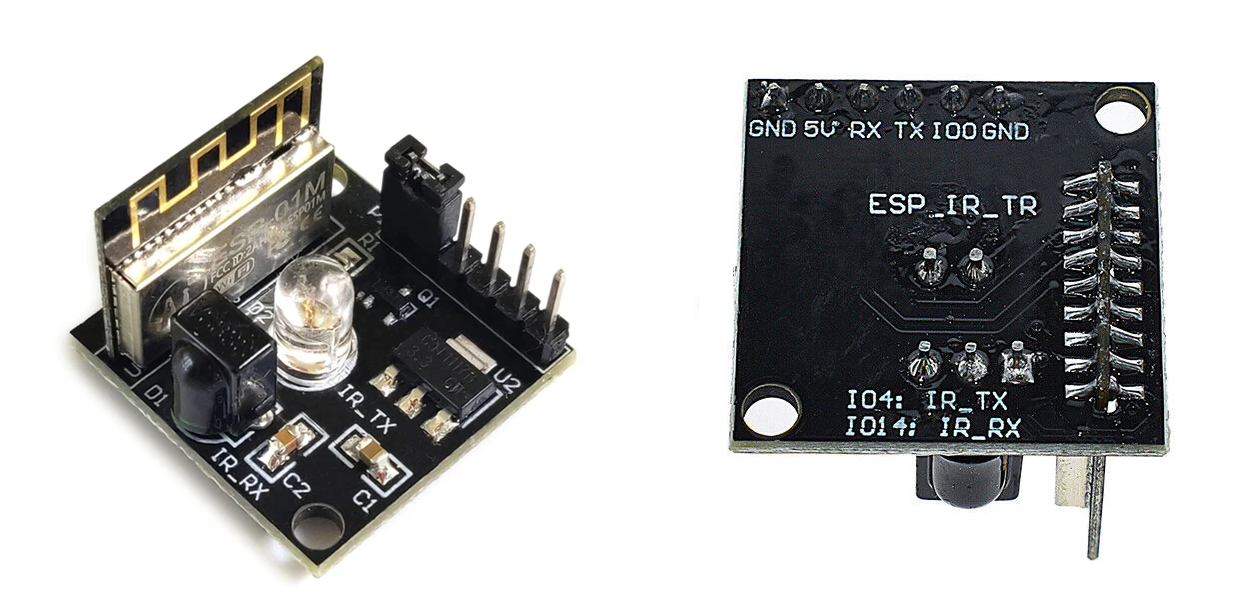
Breve introducción al transceptor IR ESP8285 ESP-01M
Un módulo transceptor inalámbrico WIFI ESP8285 con infrarrojos es una placa de circuito que combina dos funciones:
Transceptor de infrarrojos (IR): esta parte permite al módulo transmitir y recibir señales infrarrojas. El transmisor IR está conectado a GPIO4 y el receptor IR a GPIO14
Módulo Wi-Fi ESP8285: es un chip independiente de la placa que permite al módulo conectarse a una red Wi-Fi. El ESP8285 es un ESP8266 con 1M de flash que soporta temperaturas altas, de hasta 125 grados Celsius.
Para subir el firmware : conecta el jumper entre GPIO01 y GND.
Para ejecutar el firmware : quita el jumper y vuelve a conectar el programador USB
Cableado
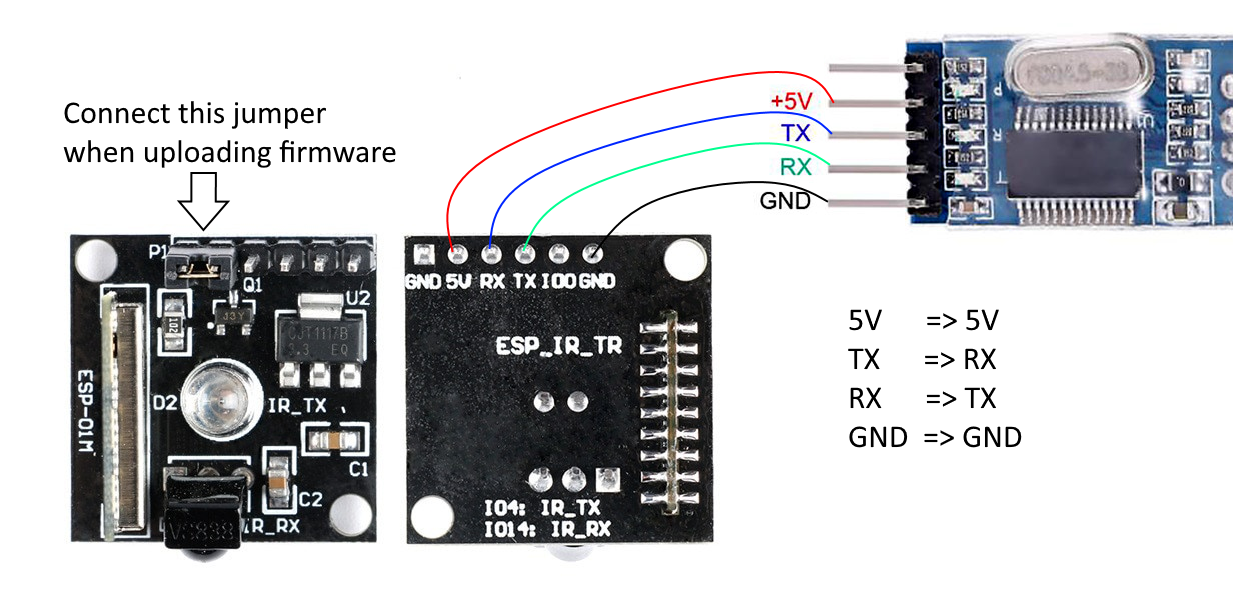
| ESP8285 | TTL |
|---|---|
| 5V | 5V |
| GND | GND |
| TX | RX |
| RX | TX |
Antes de integrarlo con Sinric Pro, es importante comprobar que el relé está bien cableado y que puedes grabar señales IR.
Paso 1: Grabar señales IR
-
Instala IRremoteESP8266
-
Haz clic en los elementos de menú “Sketch” -> “Include Library” -> “Manage Libraries…”.
-
Escribe
IRremoteESP8266en el cuadro de búsqueda “Filter your search…”, arriba a la derecha. -
Haz clic en el resultado
IRremoteESP8266de la búsqueda. -
Selecciona la versión que quieres instalar y haz clic en
Install.
-
-
Conecta el jumper entre
GPIO0yGNDpara subir el firmware. -
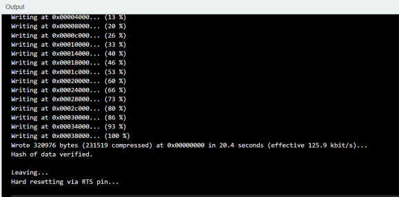
Sube el sketch IRrecvDumpV3 No hace falta modificarlo. Ya usa los pines GPIO correctos.
-
Quita el jumper que une
GPIO0conGNDy vuelve a conectar el programador USB. Ahora el chip ESP ejecutará el sketchIRrecvDumpV3. Configura la velocidad del Monitor serie de Arduino en115200para ver los registros. -
Es el momento de grabar el botón de encendido del mando a distancia de tu televisor.
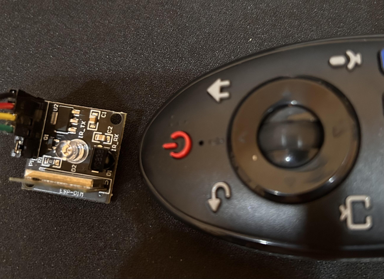
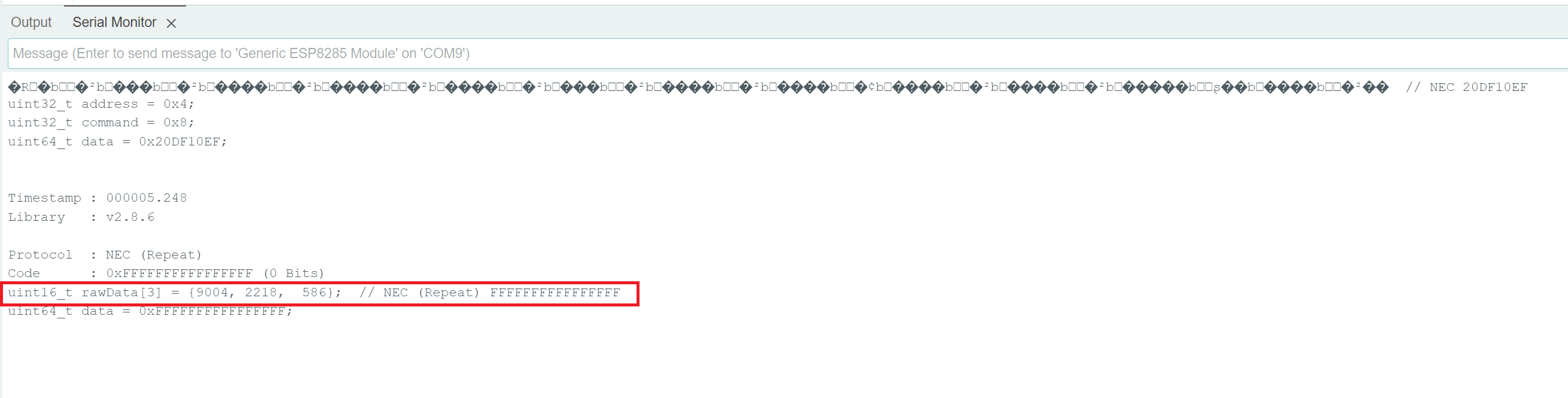
En el Monitor serie de Arduino aparecerán los códigos IR de esta forma.
Copia el array rawData
Paso 2: Enviar señales IR
#include <Arduino.h>
#include <IRremoteESP8266.h>
#include <IRsend.h>

const uint16_t kIrLed = 4;

IRsend irsend(kIrLed);

uint16_t rawData[3] = {9004, 2218,  586};  // TODO: Change this to your remote control power button

void setup() {
  irsend.begin();
  Serial.begin(115200);
}

void loop() {
  Serial.println("a rawData capture from dump");
  irsend.sendRaw(rawData, 3 /* IR len */, 38 /* kHz */);  // TODO: adjust IR len according to rawData length.
  delay(2000);
}
Sube el sketch anterior y quita el jumper para ejecutar el firmware.
Cuando el sketch envíe la señal, el televisor debería encenderse o apagarse. Ahora puedes repetir el proceso para grabar otros botones, como subir y bajar el volumen, silenciar, etc.
Paso 3 : Crea un dispositivo TV nuevo en Sinric Pro
-
Inicia sesión en tu cuenta de Sinric Pro, abre el menú Devices a la izquierda y haz clic en el botón Add Device (arriba a la izquierda).
-
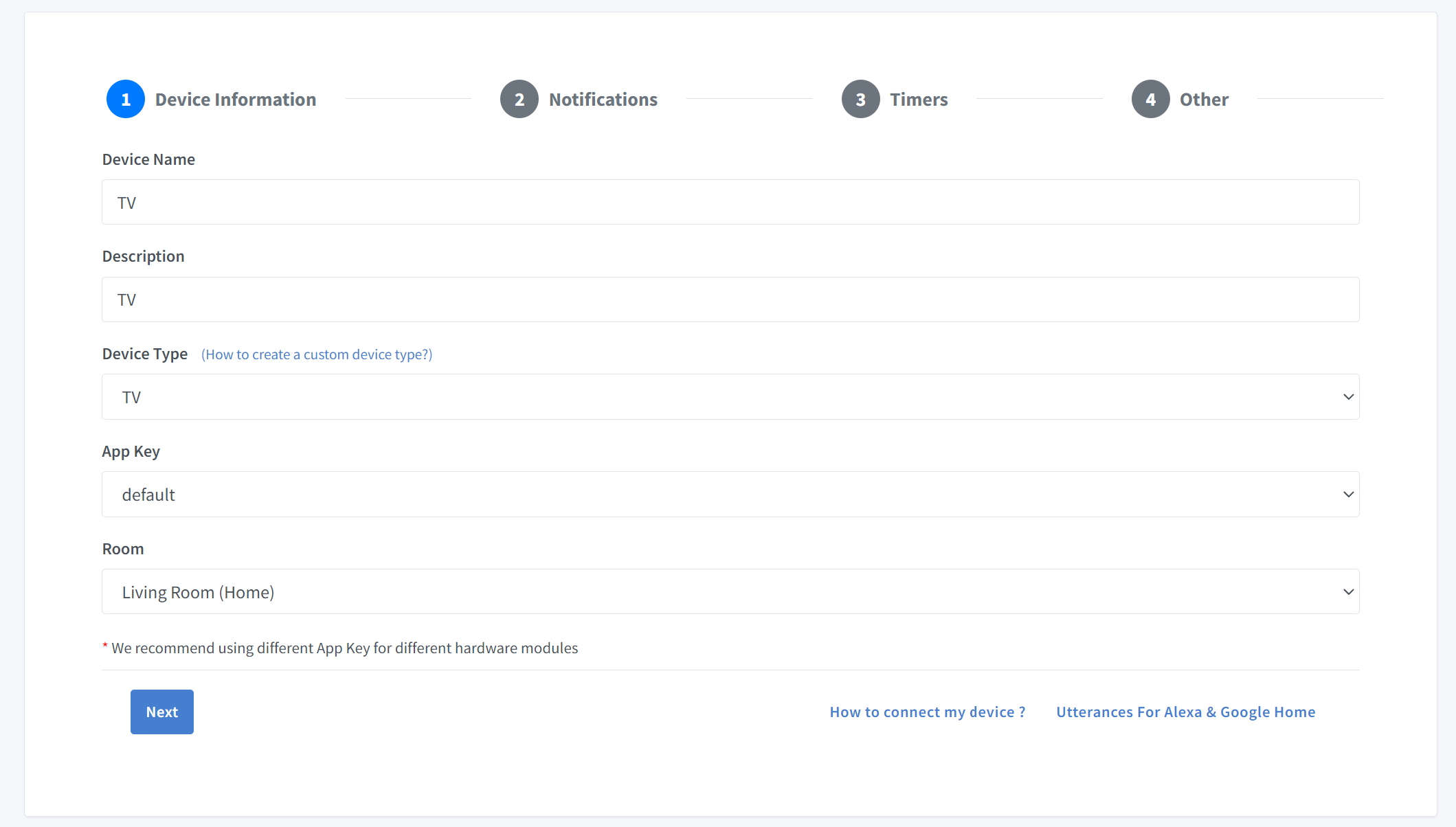
Escribe el nombre del dispositivo TV, la descripción TV y selecciona el tipo de dispositivo TV.
-
Haz clic en Others y después en Save
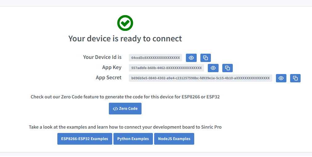
- Copia Device Id, App Key y App Secret Mantén estos valores seguros. ¡NO LOS COMPARTAS EN FOROS PÚBLICOS!
Paso 2 : Programación
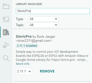
2.1 Instala la librería Sinric Pro
2.2 Código completo
Ahora podemos completar el sketch de TV de SinricPro con los códigos IR.
// #define ENABLE_DEBUG
#define SINRICPRO_NOSSL

#ifdef ENABLE_DEBUG
  #define DEBUG_ESP_PORT Serial
  #define NODEBUG_WEBSOCKETS
  #define NDEBUG
#endif

#include <Arduino.h>
#include <ESP8266WiFi.h>
#include <IRremoteESP8266.h>
#include <IRsend.h>

#include "SinricPro.h"
#include "SinricProTV.h"

#define WIFI_SSID         "YOUR-WIFI-SSID"
#define WIFI_PASS         "YOUR-WIFI-PASSWORD"
#define APP_KEY           "YOUR-APP-KEY"      // Should look like "de0bxxxx-1x3x-4x3x-ax2x-5dabxxxxxxxx"
#define APP_SECRET        "YOUR-APP-SECRET"   // Should look like "5f36xxxx-x3x7-4x3x-xexe-e86724a9xxxx-4c4axxxx-3x3x-x5xe-x9x3-333d65xxxxxx"
#define TV_ID             "YOUR-DEVICE-ID"    // Should look like "5dc1564130xxxxxxxxxxxxxx"
#define BAUD_RATE         115200

const uint16_t kIrLed = 4;
IRsend irsend(kIrLed);

bool tvPowerState;

bool onPowerState(const String &deviceId, bool &state) {
  Serial.printf("TV turned %s\r\n", state?"on":"off");
  tvPowerState = state; // set powerState

  /*
    Protocol  : NEC
    Code      : 0x20DF10EF (32 Bits)
    uint16_t rawData[71] = {9032, 4476,  582, 544,  582, 546,  582, 1652,  582, 546,  582, 544,  582, 546,  582, 546,  582, 546,  582, 1654,  582, 1654,  582, 544,  582, 1654,  582, 1654,  582, 1654,  582, 1654,  582, 1654,  582, 546,  582, 544,  584, 544,  582, 1654,  582, 546,  582, 546,  582, 546,  582, 546,  582, 1654,  582, 1654,  582, 1652,  582, 546,  582, 1654,  582, 1654,  582, 1654,  582, 1654,  582, 41158,  9004, 2222,  582};  // NEC 20DF10EF
    uint32_t address = 0x4;
    uint32_t command = 0x8;
    uint64_t data = 0x20DF10EF;
  */

  uint16_t rawData[71] = {9032, 4476,  582, 544,  582, 546,  582, 1652,  582, 546,  582, 544,  582, 546,  582, 546,  582, 546,  582, 1654,  582, 1654,  582, 544,  582, 1654,  582, 1654,  582, 1654,  582, 1654,  582, 1654,  582, 546,  582, 544,  584, 544,  582, 1654,  582, 546,  582, 546,  582, 546,  582, 546,  582, 1654,  582, 1654,  582, 1652,  582, 546,  582, 1654,  582, 1654,  582, 1654,  582, 1654,  582, 41158,  9004, 2222,  582};  // NEC 20DF10EF
  irsend.sendRaw(rawData, 71 /* IR len */, 38 /* kHz */);

  return true;
}

// setup function for WiFi connection
void setupWiFi() {
  Serial.printf("\r\n[Wifi]: Connecting");

  #if defined(ESP8266)
    WiFi.setSleepMode(WIFI_NONE_SLEEP);
    WiFi.setAutoReconnect(true);
  #elif defined(ESP32)
    WiFi.setSleep(false);
    WiFi.setAutoReconnect(true);
  #endif

  WiFi.begin(WIFI_SSID, WIFI_PASS);

  while (WiFi.status() != WL_CONNECTED) {
    Serial.printf(".");
    delay(250);
  }
  IPAddress localIP = WiFi.localIP();
  Serial.printf("connected!\r\n[WiFi]: IP-Address is %d.%d.%d.%d\r\n", localIP[0], localIP[1], localIP[2], localIP[3]);
}

// setup function for SinricPro
void setupSinricPro() {
  // add device to SinricPro
  SinricProTV& myTV = SinricPro[TV_ID];

  // set callback functions to device
  myTV.onPowerState(onPowerState);

  // For other https://github.com/sinricpro/esp8266-esp32-sdk/blob/master/examples/TV/TV.ino
  // myTV.onAdjustVolume(onAdjustVolume);
  // myTV.onChangeChannel(onChangeChannel);
  // myTV.onChangeChannelNumber(onChangeChannelNumber);
  // myTV.onMediaControl(onMediaControl);
  // myTV.onMute(onMute);
  // myTV.onSelectInput(onSelectInput);
  // myTV.onSetVolume(onSetVolume);
  // myTV.onSkipChannels(onSkipChannels);

  // setup SinricPro
  SinricPro.onConnected([](){ Serial.printf("Connected to SinricPro\r\n"); });
  SinricPro.onDisconnected([](){ Serial.printf("Disconnected from SinricPro\r\n"); });
  SinricPro.begin(APP_KEY, APP_SECRET);
}

void setupIR() {
  irsend.begin();
}

// main setup function
void setup() {
  setupIR();

  Serial.begin(BAUD_RATE); Serial.printf("\r\n\r\n");

  setupWiFi();
  setupSinricPro();
}

void loop() {
  SinricPro.handle();
}
Ver este código en GitHub Gist
Ahora también deberías poder controlar el televisor desde la app Sinric Pro, Google Home y Alexa.
Solución de problemas
Consulta nuestra página de Solución de problemas para ver posibles soluciones a tu problema.
Tutoriales relacionados
- Cómo controlar un ESP32 o ESP8266 con Alexa y Google Home
- Dispositivos RF de 433MHz con un transmisor RF
- Tutorial del interruptor, parte 1: encender y apagar un relé
Este documento es de código abierto. ¿Has visto una errata? Crea una issue