


RobotDyn AC Light Dimmer with ESP32 or ESP8266 for Alexa and Google Home
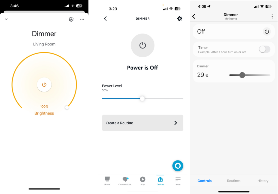
In this section we’ll walk through creating a Light dimmer with RobotDyn and then control the light brightness via Alexa, GoogleHome or SmartThings.
Prerequisites :
- ESP32 or ESP8266 x 1.
- RobotDyn AC Light Dimmer.
- Dimmable Light Bulb.
- Jumper Wires.
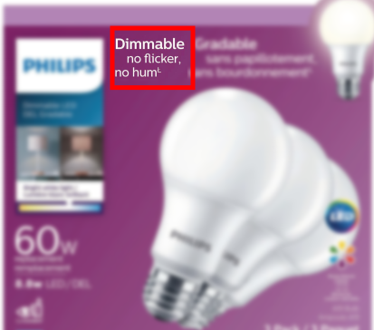
Not all the light bulbs are dimmable. Please check the manufacturer’s label to see if the bulb is dimmable.
Quick introduction to RobotDyn AC Light Dimmer Module
The RobotDyn AC Light Dimmer Module is a device that allows you to control the brightness of AC lights using a microcontroller. It is a small and easy-to-use module that can be used with microcontrollers, such as the ESP8266, ESP32. The module works by using a triac to control the flow of current to the light bulb. The triac is a semiconductor device that can be used to switch AC current on and off. The RobotDyn AC Light Dimmer Module uses a PWM signal to control the triac, which in turn controls the brightness of the light bulb.
Wiring RobotDyn AC Light Dimmer
You can use the below pin mapping table to connect your ESP32/ESP8266 with RobotDyn AC Light Dimmer module.
 *  +---------------+-------------------------+-------------------------+
 *  |   Board       | INPUT Pin               | OUTPUT Pin              |
 *  |               | Zero-Cross              | PWM                     |
 *  +---------------+-------------------------+-------------------------+
 *  | ESP8266       | D1(IO5),    D2(IO4),    | D0(IO16),   D1(IO5),    |
 *  |               | D5(IO14),   D6(IO12),   | D2(IO4),    D5(IO14),   |
 *  |               | D7(IO13),   D8(IO15),   | D6(IO12),   D7(IO13),   |
 *  |               |                         | D8(IO15)                |
 *  +---------------+-------------------------+-------------------------+
 *  | ESP32         | 4(GPI36),   6(GPI34),   | 8(GPO32),   9(GP033),   |
 *  |               | 5(GPI39),   7(GPI35),   | 10(GPIO25), 11(GPIO26), |
 *  |               | 8(GPO32),   9(GP033),   | 12(GPIO27), 13(GPIO14), |
 *  |               | 10(GPI025), 11(GPIO26), | 14(GPIO12), 16(GPIO13), |
 *  |               | 12(GPIO27), 13(GPIO14), | 23(GPIO15), 24(GPIO2),  |
 *  |               | 14(GPIO12), 16(GPIO13), | 25(GPIO0),  26(GPIO4),  |
 *  |               | 21(GPIO7),  23(GPIO15), | 27(GPIO16), 28(GPIO17), |
 *  |               | 24(GPIO2),  25(GPIO0),  | 29(GPIO5),  30(GPIO18), |
 *  |               | 26(GPIO4),  27(GPIO16), | 31(GPIO19), 33(GPIO21), |
 *  |               | 28(GPIO17), 29(GPIO5),  | 34(GPIO3),  35(GPIO1),  |
 *  |               | 30(GPIO18), 31(GPIO19), | 36(GPIO22), 37(GPIO23), |
 *  |               | 33(GPIO21), 35(GPIO1),  |                         |
 *  |               | 36(GPIO22), 37(GPIO23), |                         |
 *  +---------------+-------------------------+-------------------------+
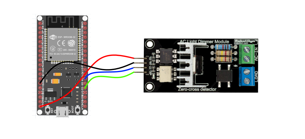
Connect the RobotDyn module to the microcontroller as follows:
- VCC pin to the microcontroller’s 5V pin (3.3V does not seems to work).
- GND pin to the ESP32’s GND pin.
- PWM pin to a digital pin 2 on the microcontroller.
- Z-C pin to a digital pin 4 on the microcontroller.
| MCU | Zero Cross Pin | PWM/ADC Pin |
|---|---|---|
| ESP32 | 4 | 2 |
RBDdimmer library (RBDdimmer.h)
The code in this tutorial uses RobotDyn’s RBDdimmer library. Download it from GitHub as a ZIP file and add it in Arduino IDE with Sketch > Include Library > Add .ZIP Library.
dimmerLamp constructor parameters
#include <RBDdimmer.h>

// ESP32, ESP8266, Arduino Due: you choose both pins
dimmerLamp dimmer(outputPin, zeroCrossPin);

// Arduino UNO, Nano, Mega, Leonardo, M0/Zero: the zero-cross pin is fixed
dimmerLamp dimmer(outputPin);
| Parameter | Description |
|---|---|
outputPin |
GPIO connected to the module’s PWM (DIM/PSM) pin |
zeroCrossPin |
GPIO connected to the module’s Z-C pin. Only on boards where the zero-cross pin can be changed (ESP32, ESP8266, Arduino Due). On UNO, Nano and Mega it is fixed to D2, on Leonardo and M0/Zero to D7 |
On an ESP32, GPIO 34, 35, 36 and 39 are input only. They can be used for the zero-cross pin but not for the PWM output pin.
Functions
| Function | Description |
|---|---|
begin(NORMAL_MODE, ON) |
Starts the dimmer. First parameter: NORMAL_MODE or TOGGLE_MODE. Second parameter: ON or OFF |
setPower(int power) |
Sets the brightness from 0 to 100 (%) |
getPower() |
Returns the current brightness (0 to 100) |
setState(ON) / setState(OFF) |
Turns the output on or off |
getState() |
Returns the current state |
changeState() |
Switches to the opposite state |
setMode(NORMAL_MODE) / getMode() |
Sets or returns the working mode |
toggleSettings(int minValue, int maxValue) |
In TOGGLE_MODE, fades up and down between the two values |
Example:
#include <RBDdimmer.h>

#define PWM_PIN        2
#define ZERO_CROSS_PIN 4

dimmerLamp dimmer(PWM_PIN, ZERO_CROSS_PIN);

void setup() {
  dimmer.begin(NORMAL_MODE, ON);
  dimmer.setPower(50); // 50% brightness
}

void loop() {}
Let’s verify that RobotDyn AC Light Dimmer Module is wired correctly and working.
#include <RBDdimmer.h> //https://github.com/RobotDynOfficial/RBDDimmer

const int ZC_PIN  = 0;
const int PWM_PIN  = 2;

int MIN_POWER  = 0;
int MAX_POWER  = 80;
int POWER_STEP  = 2;
int power  = 0;

dimmerLamp acd(PWM_PIN, ZC_PIN);

void setup(){
    Serial.begin(115200);
    delay(100);
    acd.begin(NORMAL_MODE, ON);
}

void loop(){
  for(power=MIN_POWER;power<=MAX_POWER;power+=POWER_STEP){
    acd.setPower(power);
    delay(100);
  }

  for(power=MAX_POWER;power>=MIN_POWER;power-=POWER_STEP){
    acd.setPower(power);
    delay(100);
  }
}
Arduino IDE Serial Monitor will show the dimming like this:
Step 1 : Create a new device in Sinric Pro
- Login to your Sinric Pro account, go to Devices menu on your left and click Add Device button (On top left).
- Enter the device name Dimmer, description Dimmer and select the device type as Switch With Dimming.
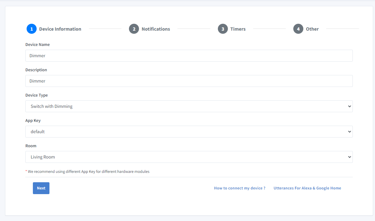
-
Click Others tab and Click Save
-
Next screen will show the credentials required to connect the device you just created.
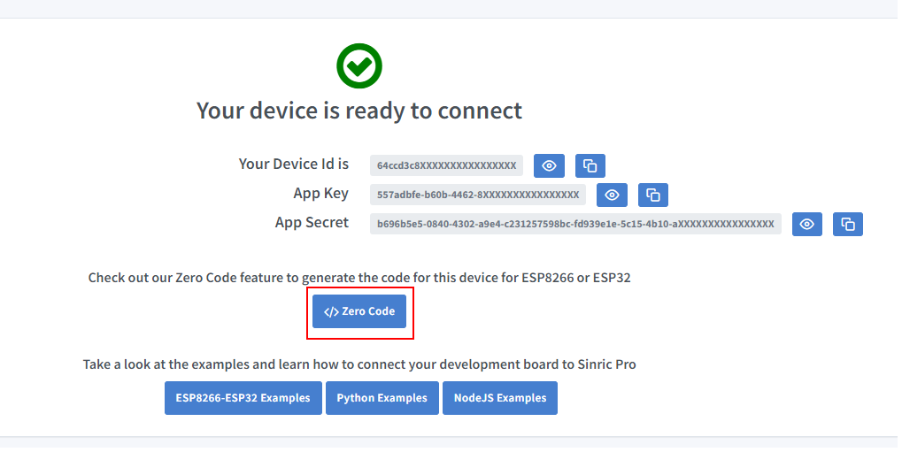
- Copy the Device Id, App Key and App Secret Keep these values secure. DO NOT SHARE THEM ON PUBLIC FORUMS !
Step 2 : Connect to Sinric Pro
Step 2.1 Install Sinric Pro Library
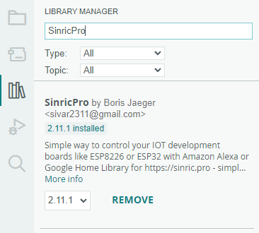
2.2 Complete Code
//Uncomment the following line to enable serial debug output
//#define ENABLE_DEBUG

#ifdef ENABLE_DEBUG
  #define DEBUG_ESP_PORT Serial
  #define NODEBUG_WEBSOCKETS
  #define NDEBUG
#endif

#include <Arduino.h>
#if defined(ESP8266)
  #include <ESP8266WiFi.h>
#elif defined(ESP32) || defined(ARDUINO_ARCH_RP2040)
  #include <WiFi.h>
#endif

#include <RBDdimmer.h> //https://github.com/RobotDynOfficial/RBDDimmer

#include "SinricPro.h"
#include "SinricProDimSwitch.h"

#define WIFI_SSID         ""
#define WIFI_PASS         ""
#define APP_KEY           ""   // Should look like "de0bxxxx-1x3x-4x3x-ax2x-5dabxxxxxxxx"
#define APP_SECRET        ""   // Should look like "5f36xxxx-x3x7-4x3x-xexe-e86724a9xxxx-4c4axxxx-3x3x-x5xe-x9x3-333d65xxxxxx"
#define DIMSWITCH_ID      ""   // Should look like "5dc1564130xxxxxxxxxxxxxx"
#define BAUD_RATE         115200                // Change baudrate to your need

const int ZC_PIN  = 4;
const int PWM_PIN  = 2;
const int MIN_POWER  = 0;
const int MAX_POWER  = 80;
int power  = 0;

dimmerLamp acd(PWM_PIN, ZC_PIN);

// we use a struct to store all states and values for our dimmable switch
struct {
  bool powerState = false;
  int powerLevel = 0;
} device_state;

void setPWM(int powerLevel) {
   int power = map(powerLevel, 0, 100, MIN_POWER, MAX_POWER); // Map power level from 0 to 100, to a value between 0 to 80
   acd.setPower(power);
   delay(30);
}

bool onPowerState(const String &deviceId, bool &state) {
  Serial.printf("Device %s power turned %s \r\n", deviceId.c_str(), state?"on":"off");
  device_state.powerState = state;
  setPWM(state ? 100: 0);
  return true; // request handled properly
}

bool onPowerLevel(const String &deviceId, int &powerLevel) {
  device_state.powerLevel = powerLevel;
  setPWM(powerLevel);
  Serial.printf("Device %s power level changed to %d\r\n", deviceId.c_str(), device_state.powerLevel);
  return true;
}

bool onAdjustPowerLevel(const String &deviceId, int &levelDelta) {
  device_state.powerLevel += levelDelta;
  Serial.printf("Device %s power level changed about %i to %d\r\n", deviceId.c_str(), levelDelta, device_state.powerLevel);
  levelDelta = device_state.powerLevel;
  setPWM(levelDelta);
  return true;
}

void setupWiFi() {
  Serial.printf("\r\n[Wifi]: Connecting");

  #if defined(ESP8266)
    WiFi.setSleepMode(WIFI_NONE_SLEEP);
    WiFi.setAutoReconnect(true);
  #elif defined(ESP32)
    WiFi.setSleep(false);
    WiFi.setAutoReconnect(true);
  #endif

  WiFi.begin(WIFI_SSID, WIFI_PASS);

  while (WiFi.status() != WL_CONNECTED) {
    Serial.printf(".");
    delay(250);
  }
  IPAddress localIP = WiFi.localIP();
  Serial.printf("connected!\r\n[WiFi]: IP-Address is %d.%d.%d.%d\r\n", localIP[0], localIP[1], localIP[2], localIP[3]);
}

void setupSinricPro() {
  SinricProDimSwitch &myDimSwitch = SinricPro[DIMSWITCH_ID];

  // set callback function to device
  myDimSwitch.onPowerState(onPowerState);
  myDimSwitch.onPowerLevel(onPowerLevel);
  myDimSwitch.onAdjustPowerLevel(onAdjustPowerLevel);

  // setup SinricPro
  SinricPro.onConnected([](){ Serial.printf("Connected to SinricPro\r\n"); });
  SinricPro.onDisconnected([](){ Serial.printf("Disconnected from SinricPro\r\n"); });
  SinricPro.begin(APP_KEY, APP_SECRET);
}

void setupRBDdimmer(){
   acd.begin(NORMAL_MODE, ON);
}

// main setup function
void setup() {
  Serial.begin(BAUD_RATE); Serial.printf("\r\n\r\n");
  setupRBDdimmer();
  setupWiFi();
  setupSinricPro();
}

void loop() {
  SinricPro.handle();
}
Troubleshooting
- Does not dim ? Please check the manufacturer’s label to see if the light bulb is dimmable.
- PWM not working ?
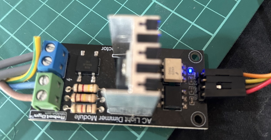
Above LED lights up when the module recevice the PWM signal from MCU.
- Please refer to our Troubleshooting page for more details.
Related tutorials
- How to control an ESP32 or ESP8266 with Alexa and Google Home
- Dimmable switch with a YYAC-3S module
- RGB LED strip (5050)
- Switch tutorial part 1: turn a relay on and off
This document is open source. See a typo? Please create an issue