


Regulador de luz AC RobotDyn con ESP32 o ESP8266 para Alexa y Google Home
En esta sección veremos cómo crear un regulador de luz con RobotDyn y cómo controlar después el brillo de la luz con Alexa, GoogleHome o SmartThings.
Requisitos previos :
- ESP32 o ESP8266 x 1.
- Regulador de luz AC RobotDyn.
- Bombilla regulable.
- Cables puente.
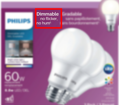
No todas las bombillas son regulables. Revisa la etiqueta del fabricante para comprobar si la bombilla es regulable.
Introducción rápida al módulo regulador de luz AC RobotDyn
El módulo regulador de luz AC RobotDyn es un dispositivo que te permite controlar el brillo de luces de corriente alterna con un microcontrolador. Es un módulo pequeño y fácil de usar que funciona con microcontroladores como el ESP8266 o el ESP32. El módulo utiliza un triac para controlar el paso de corriente hacia la bombilla. El triac es un dispositivo semiconductor que sirve para conectar y desconectar la corriente alterna. El módulo regulador de luz AC RobotDyn usa una señal PWM para controlar el triac, que a su vez controla el brillo de la bombilla.
Cableado del regulador de luz AC RobotDyn
Puedes usar la siguiente tabla de asignación de pines para conectar tu ESP32/ESP8266 al módulo regulador de luz AC RobotDyn.
 *  +---------------+-------------------------+-------------------------+
 *  |   Board       | INPUT Pin               | OUTPUT Pin              |
 *  |               | Zero-Cross              | PWM                     |
 *  +---------------+-------------------------+-------------------------+
 *  | ESP8266       | D1(IO5),    D2(IO4),    | D0(IO16),   D1(IO5),    |
 *  |               | D5(IO14),   D6(IO12),   | D2(IO4),    D5(IO14),   |
 *  |               | D7(IO13),   D8(IO15),   | D6(IO12),   D7(IO13),   |
 *  |               |                         | D8(IO15)                |
 *  +---------------+-------------------------+-------------------------+
 *  | ESP32         | 4(GPI36),   6(GPI34),   | 8(GPO32),   9(GP033),   |
 *  |               | 5(GPI39),   7(GPI35),   | 10(GPIO25), 11(GPIO26), |
 *  |               | 8(GPO32),   9(GP033),   | 12(GPIO27), 13(GPIO14), |
 *  |               | 10(GPI025), 11(GPIO26), | 14(GPIO12), 16(GPIO13), |
 *  |               | 12(GPIO27), 13(GPIO14), | 23(GPIO15), 24(GPIO2),  |
 *  |               | 14(GPIO12), 16(GPIO13), | 25(GPIO0),  26(GPIO4),  |
 *  |               | 21(GPIO7),  23(GPIO15), | 27(GPIO16), 28(GPIO17), |
 *  |               | 24(GPIO2),  25(GPIO0),  | 29(GPIO5),  30(GPIO18), |
 *  |               | 26(GPIO4),  27(GPIO16), | 31(GPIO19), 33(GPIO21), |
 *  |               | 28(GPIO17), 29(GPIO5),  | 34(GPIO3),  35(GPIO1),  |
 *  |               | 30(GPIO18), 31(GPIO19), | 36(GPIO22), 37(GPIO23), |
 *  |               | 33(GPIO21), 35(GPIO1),  |                         |
 *  |               | 36(GPIO22), 37(GPIO23), |                         |
 *  +---------------+-------------------------+-------------------------+
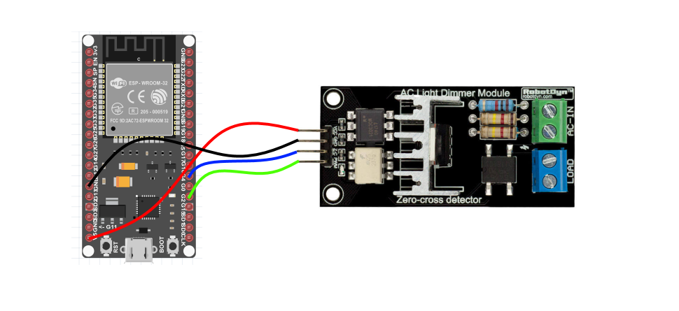
Conecta el módulo RobotDyn al microcontrolador de la siguiente manera:
- Pin VCC al pin de 5V del microcontrolador (con 3.3V no parece funcionar).
- Pin GND al pin GND del ESP32.
- Pin PWM al pin digital 2 del microcontrolador.
- Pin Z-C al pin digital 4 del microcontrolador.
| MCU | Pin de cruce por cero | Pin PWM/ADC |
|---|---|---|
| ESP32 | 4 | 2 |
Librería RBDdimmer (RBDdimmer.h)
El código de este tutorial usa la librería RBDdimmer de RobotDyn. Descárgala de GitHub como archivo ZIP y añádela en Arduino IDE con Programa > Incluir biblioteca > Añadir biblioteca .ZIP.
Parámetros del constructor dimmerLamp
#include <RBDdimmer.h>

// ESP32, ESP8266, Arduino Due: you choose both pins
dimmerLamp dimmer(outputPin, zeroCrossPin);

// Arduino UNO, Nano, Mega, Leonardo, M0/Zero: the zero-cross pin is fixed
dimmerLamp dimmer(outputPin);
| Parámetro | Descripción |
|---|---|
outputPin |
GPIO conectado al pin PWM (DIM/PSM) del módulo |
zeroCrossPin |
GPIO conectado al pin Z-C del módulo. Solo en las placas en las que se puede cambiar el pin de cruce por cero (ESP32, ESP8266, Arduino Due). En UNO, Nano y Mega está fijado en D2; en Leonardo y M0/Zero, en D7 |
En un ESP32, los GPIO 34, 35, 36 y 39 son solo de entrada. Se pueden usar para el pin de cruce por cero, pero no para el pin de salida PWM.
Funciones
| Función | Descripción |
|---|---|
begin(NORMAL_MODE, ON) |
Inicia el regulador. Primer parámetro: NORMAL_MODE o TOGGLE_MODE. Segundo parámetro: ON u OFF |
setPower(int power) |
Ajusta el brillo de 0 a 100 (%) |
getPower() |
Devuelve el brillo actual (de 0 a 100) |
setState(ON) / setState(OFF) |
Enciende o apaga la salida |
getState() |
Devuelve el estado actual |
changeState() |
Cambia al estado opuesto |
setMode(NORMAL_MODE) / getMode() |
Establece o devuelve el modo de funcionamiento |
toggleSettings(int minValue, int maxValue) |
En TOGGLE_MODE, sube y baja el brillo gradualmente entre los dos valores |
Ejemplo:
#include <RBDdimmer.h>

#define PWM_PIN        2
#define ZERO_CROSS_PIN 4

dimmerLamp dimmer(PWM_PIN, ZERO_CROSS_PIN);

void setup() {
  dimmer.begin(NORMAL_MODE, ON);
  dimmer.setPower(50); // 50% brightness
}

void loop() {}
Vamos a comprobar que el módulo regulador de luz AC RobotDyn está bien cableado y funciona.
#include <RBDdimmer.h> //https://github.com/RobotDynOfficial/RBDDimmer

const int ZC_PIN  = 0;
const int PWM_PIN  = 2;

int MIN_POWER  = 0;
int MAX_POWER  = 80;
int POWER_STEP  = 2;
int power  = 0;

dimmerLamp acd(PWM_PIN, ZC_PIN);

void setup(){
    Serial.begin(115200);
    delay(100);
    acd.begin(NORMAL_MODE, ON);
}

void loop(){
  for(power=MIN_POWER;power<=MAX_POWER;power+=POWER_STEP){
    acd.setPower(power);
    delay(100);
  }

  for(power=MAX_POWER;power>=MIN_POWER;power-=POWER_STEP){
    acd.setPower(power);
    delay(100);
  }
}
Ver este código en GitHub Gist
El Monitor Serie de Arduino IDE mostrará la regulación así:
Paso 1 : Crea un nuevo dispositivo en Sinric Pro
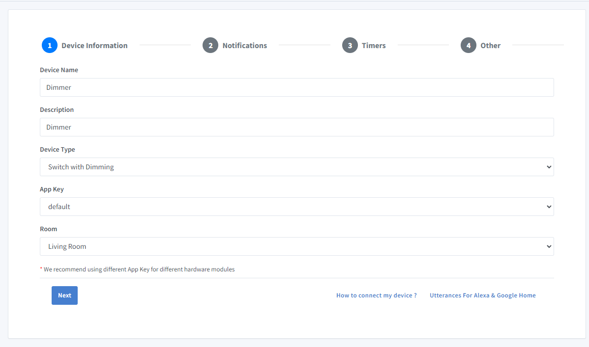
- Inicia sesión en tu cuenta de Sinric Pro, ve al menú Devices a la izquierda y haz clic en el botón Add Device (arriba a la izquierda).
- Escribe el nombre del dispositivo Dimmer, la descripción Dimmer y selecciona el tipo de dispositivo Switch With Dimming.
-
Haz clic en la pestaña Others y luego en Save
-
La siguiente pantalla mostrará las credenciales necesarias para conectar el dispositivo que acabas de crear.
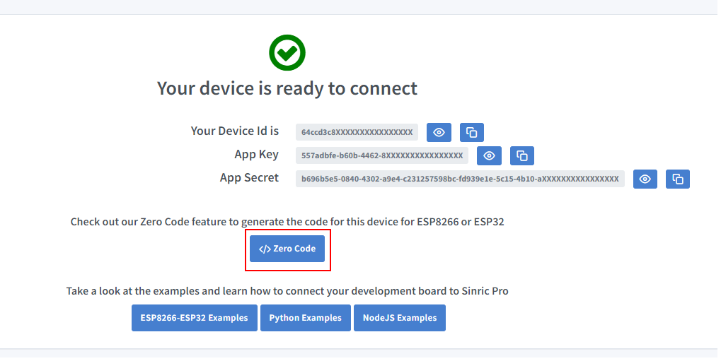
- Copia Device Id, App Key y App Secret Mantén estos valores seguros. ¡NO LOS COMPARTAS EN FOROS PÚBLICOS!
Paso 2 : Conéctate a Sinric Pro
Paso 2.1 Instala la librería Sinric Pro
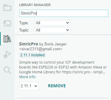
2.2 Código completo
//Uncomment the following line to enable serial debug output
//#define ENABLE_DEBUG

#ifdef ENABLE_DEBUG
  #define DEBUG_ESP_PORT Serial
  #define NODEBUG_WEBSOCKETS
  #define NDEBUG
#endif

#include <Arduino.h>
#if defined(ESP8266)
  #include <ESP8266WiFi.h>
#elif defined(ESP32) || defined(ARDUINO_ARCH_RP2040)
  #include <WiFi.h>
#endif

#include <RBDdimmer.h> //https://github.com/RobotDynOfficial/RBDDimmer

#include "SinricPro.h"
#include "SinricProDimSwitch.h"

#define WIFI_SSID         ""
#define WIFI_PASS         ""
#define APP_KEY           ""   // Should look like "de0bxxxx-1x3x-4x3x-ax2x-5dabxxxxxxxx"
#define APP_SECRET        ""   // Should look like "5f36xxxx-x3x7-4x3x-xexe-e86724a9xxxx-4c4axxxx-3x3x-x5xe-x9x3-333d65xxxxxx"
#define DIMSWITCH_ID      ""   // Should look like "5dc1564130xxxxxxxxxxxxxx"
#define BAUD_RATE         115200                // Change baudrate to your need

const int ZC_PIN  = 4;
const int PWM_PIN  = 2;
const int MIN_POWER  = 0;
const int MAX_POWER  = 80;
int power  = 0;

dimmerLamp acd(PWM_PIN, ZC_PIN);

// we use a struct to store all states and values for our dimmable switch
struct {
  bool powerState = false;
  int powerLevel = 0;
} device_state;

void setPWM(int powerLevel) {
   int power = map(powerLevel, 0, 100, MIN_POWER, MAX_POWER); // Map power level from 0 to 100, to a value between 0 to 80
   acd.setPower(power);
   delay(30);
}

bool onPowerState(const String &deviceId, bool &state) {
  Serial.printf("Device %s power turned %s \r\n", deviceId.c_str(), state?"on":"off");
  device_state.powerState = state;
  setPWM(state ? 100: 0);
  return true; // request handled properly
}

bool onPowerLevel(const String &deviceId, int &powerLevel) {
  device_state.powerLevel = powerLevel;
  setPWM(powerLevel);
  Serial.printf("Device %s power level changed to %d\r\n", deviceId.c_str(), device_state.powerLevel);
  return true;
}

bool onAdjustPowerLevel(const String &deviceId, int &levelDelta) {
  device_state.powerLevel += levelDelta;
  Serial.printf("Device %s power level changed about %i to %d\r\n", deviceId.c_str(), levelDelta, device_state.powerLevel);
  levelDelta = device_state.powerLevel;
  setPWM(levelDelta);
  return true;
}

void setupWiFi() {
  Serial.printf("\r\n[Wifi]: Connecting");

  #if defined(ESP8266)
    WiFi.setSleepMode(WIFI_NONE_SLEEP);
    WiFi.setAutoReconnect(true);
  #elif defined(ESP32)
    WiFi.setSleep(false);
    WiFi.setAutoReconnect(true);
  #endif

  WiFi.begin(WIFI_SSID, WIFI_PASS);

  while (WiFi.status() != WL_CONNECTED) {
    Serial.printf(".");
    delay(250);
  }
  IPAddress localIP = WiFi.localIP();
  Serial.printf("connected!\r\n[WiFi]: IP-Address is %d.%d.%d.%d\r\n", localIP[0], localIP[1], localIP[2], localIP[3]);
}

void setupSinricPro() {
  SinricProDimSwitch &myDimSwitch = SinricPro[DIMSWITCH_ID];

  // set callback function to device
  myDimSwitch.onPowerState(onPowerState);
  myDimSwitch.onPowerLevel(onPowerLevel);
  myDimSwitch.onAdjustPowerLevel(onAdjustPowerLevel);

  // setup SinricPro
  SinricPro.onConnected([](){ Serial.printf("Connected to SinricPro\r\n"); });
  SinricPro.onDisconnected([](){ Serial.printf("Disconnected from SinricPro\r\n"); });
  SinricPro.begin(APP_KEY, APP_SECRET);
}

void setupRBDdimmer(){
   acd.begin(NORMAL_MODE, ON);
}

// main setup function
void setup() {
  Serial.begin(BAUD_RATE); Serial.printf("\r\n\r\n");
  setupRBDdimmer();
  setupWiFi();
  setupSinricPro();
}

void loop() {
  SinricPro.handle();
}
Ver este código en GitHub Gist
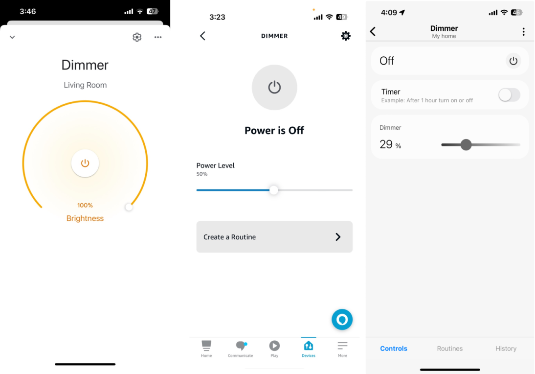
Solución de problemas
- ¿No regula? Revisa la etiqueta del fabricante para comprobar si la bombilla es regulable.
- ¿El PWM no funciona?
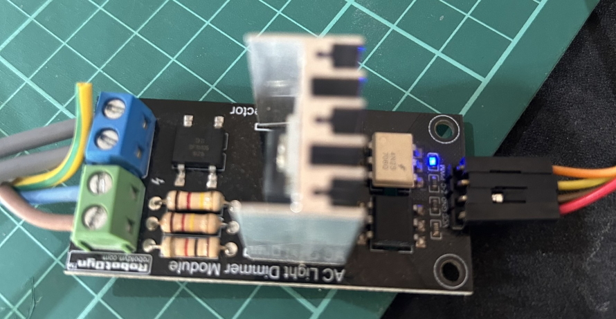
El LED de la imagen se enciende cuando el módulo recibe la señal PWM del MCU.
- Consulta nuestra página de Solución de problemas para más detalles.
Tutoriales relacionados
- Cómo controlar un ESP32 o ESP8266 con Alexa y Google Home
- Interruptor regulable con un módulo YYAC-3S
- Tira de LED RGB (5050)
- Tutorial de Switch, parte 1: enciende y apaga un relé
Este documento es de código abierto. ¿Ves un error? Por favor, crea un issue