


Controla una tira LED RGB 5050 con ESP32 o ESP8266 mediante Alexa y Google Home
En esta sección vamos a crear una tira de luz LED con un ESP32 o ESP8266 para después controlarla con Amazon Alexa, Google Home o SmartThings.
Requisitos previos :
- ESP32, ESP8266 x 1.
- MOSFET IRF540N, MOSFET STP16nF06L, transistor NPN S8050 o transistor NPN BC337 x 3
- Resistencia de 1k x 3
- Cables puente (jumper).
En este tutorial vamos a usar transistores NPN BC337.
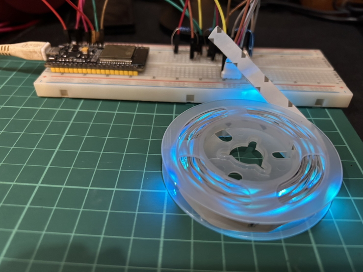
Breve introducción a las tiras LED 5050
Las tiras LED 5050 son un tipo de tira LED formada por LED individuales agrupados en conjuntos de tres. Cada conjunto de tres LED se conoce como píxel. Los píxeles están dispuestos en una tira larga y delgada que se puede cortar a la medida que necesites. Las tiras LED 5050 están disponibles en varios colores, como rojo, verde, azul, blanco y amarillo. También se pueden comprar con distintos niveles de brillo. Las tiras LED 5050 son tiras LED económicas que se parecen a las tiras Neopixel, más caras. Sin embargo, los LED de las tiras 5050 no se pueden controlar individualmente. Esto significa que solo puedes usar un color a la vez para toda la tira.
Esta tabla resume las principales diferencias entre las tiras LED 5050 y las tiras Neopixel:
| Característica | Tiras LED 5050 | Tiras Neopixel |
|---|---|---|
| Precio | Económicas | Más caras |
| LED direccionables individualmente | No | Sí |
| Animaciones | Limitadas a animaciones comunes, como el cambio de color y la atenuación | Son posibles animaciones complejas con LED individuales |
Pinout de la tira LED RGB 5050
Una tira RGB 5050 estándar (no direccionable) tiene 4 contactos: un contacto positivo compartido y un contacto por cada color.
| Contacto | Función |
|---|---|
+ (+5V o +12V) |
Positivo común (ánodo común). Conéctalo a la fuente de alimentación |
R |
Canal rojo, conmutado a masa |
G |
Canal verde, conmutado a masa |
B |
Canal azul, conmutado a masa |
- La tira es de ánodo común: un color se enciende cuando su contacto se lleva a masa. Por eso cada color se controla a través de un transistor o un MOSFET, y no directamente desde un GPIO.
- El orden de los contactos no es el mismo en todas las tiras (por ejemplo,
+ G R Bo+ R G B). Lee las etiquetas impresas en la tira junto a los contactos. - Comprueba la tensión impresa en la tira. Las tiras de 5V y de 12V tienen el mismo aspecto.
- “5050” es el tamaño del encapsulado de cada LED: 5.0 mm x 5.0 mm. Cada encapsulado contiene un LED rojo, uno verde y uno azul.
Cableado
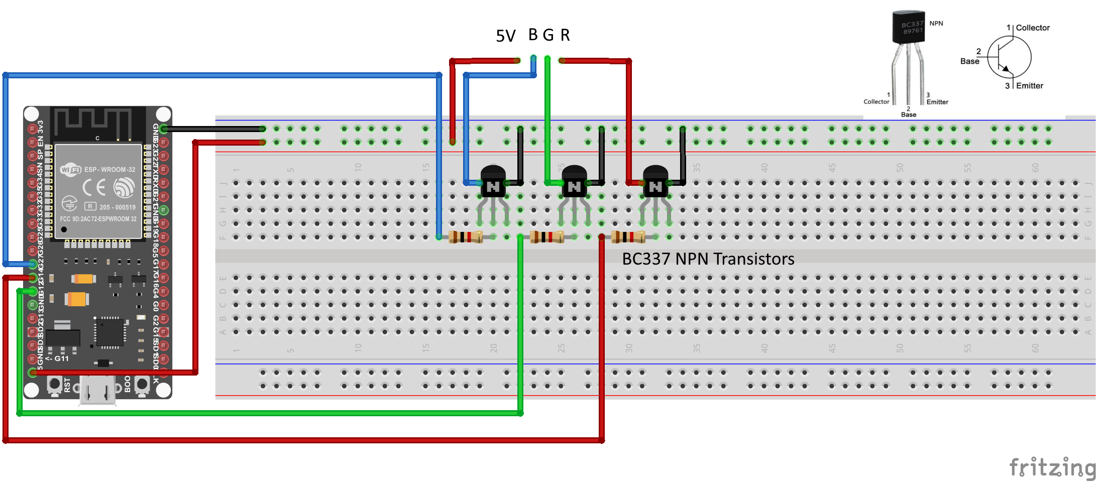
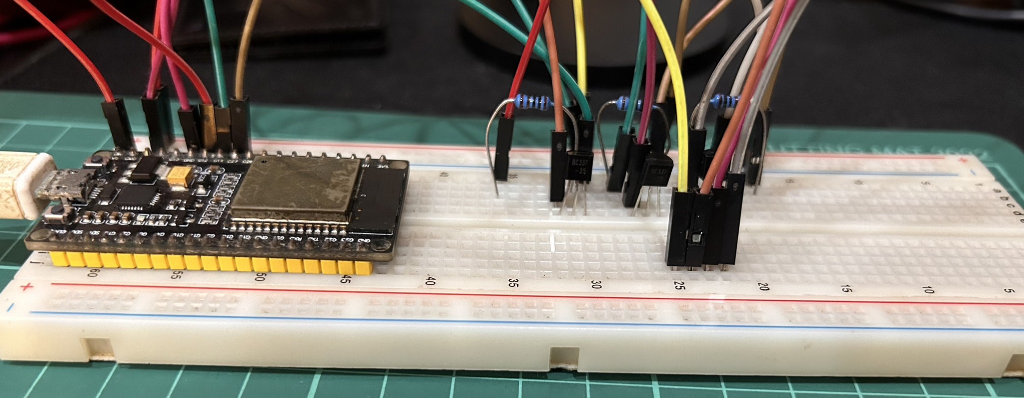
| Tira | PIN del ESP32 |
|---|---|
| 5V | 5V |
| R | 14 |
| G | 12 |
| B | 27 |
Vamos a comprobar que la tira LED está bien cableada y funciona.
// Red, green, and blue pins for PWM control
const int ledR = 14;
const int ledG = 12;
const int bluePin = 27;

uint8_t color = 0;          // a value from 0 to 255 representing the hue
uint32_t R, G, B;           // the Red Green and Blue color components
uint8_t brightness = 255;  // 255 is maximum brightness, but can be changed.  Might need 256 for common anode to fully turn off.
bool invert = false;

void hueToRGB(uint8_t hue, uint8_t brightness);

void setup() {
  Serial.begin(115200);
  delay(10);

  ledcAttachPin(ledR, 1);
  ledcAttachPin(ledG, 2);
  ledcAttachPin(ledB, 3);

  // Initialize channels
  // channels 0-15, resolution 1-16 bits, freq limits depend on resolution
  // ledcSetup(uint8_t channel, uint32_t freq, uint8_t resolution_bits);
  ledcSetup(1, 12000, 8); // 12 kHz PWM, 8-bit resolution
  ledcSetup(2, 12000, 8);
  ledcSetup(3, 12000, 8);
}

void loop(){
   for (color = 0; color < 255; color++) { // Slew through the color spectrum
    hueToRGB(color, brightness);  // call function to convert hue to RGB

    // write the RGB values to the pins
    ledcWrite(1, R); // write red component to channel 1, etc.
    ledcWrite(2, G);
    ledcWrite(3, B);

    delay(100); // full cycle of rgb over 256 colors takes 26 seconds
 }
}

// Courtesy http://www.instructables.com/id/How-to-Use-an-RGB-LED/?ALLSTEPS
// function to convert a color to its Red, Green, and Blue components.

void hueToRGB(uint8_t hue, uint8_t brightness) {
    uint16_t scaledHue = (hue * 6);
    uint8_t segment = scaledHue / 256; // segment 0 to 5 around the
                                            // color wheel
    uint16_t segmentOffset =
      scaledHue - (segment * 256); // position within the segment

    uint8_t complement = 0;
    uint16_t prev = (brightness * ( 255 -  segmentOffset)) / 256;
    uint16_t next = (brightness *  segmentOffset) / 256;

    if(invert)
    {
      brightness = 255 - brightness;
      complement = 255;
      prev = 255 - prev;
      next = 255 - next;
    }

    switch(segment ) {
    case 0:      // red
        R = brightness;
        G = next;
        B = complement;
    break;
    case 1:     // yellow
        R = prev;
        G = brightness;
        B = complement;
    break;
    case 2:     // green
        R = complement;
        G = brightness;
        B = next;
    break;
    case 3:    // cyan
        R = complement;
        G = prev;
        B = brightness;
    break;
    case 4:    // blue
        R = next;
        G = complement;
        B = brightness;
    break;
   case 5:      // magenta
    default:
        R = brightness;
        G = complement;
        B = prev;
    break;
    }
}
Ver este código en GitHub Gist
La tira LED cambiará de color de esta forma:
Paso 1 : Crea un dispositivo nuevo en Sinric Pro
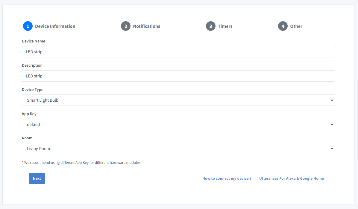
- Inicia sesión en tu cuenta de Sinric Pro, abre el menú Devices a la izquierda y haz clic en el botón Add Device (arriba a la izquierda).
- Escribe el nombre del dispositivo LED strip, la descripción My LED strip y selecciona el tipo de dispositivo Smart Light Bulb.
-
Haz clic en Next en la pestaña Notifications
-
Haz clic en la pestaña Others y después en Save
-
La siguiente pantalla muestra las credenciales necesarias para conectar el dispositivo que acabas de crear.
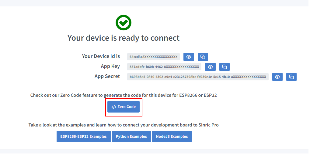
- Copia Device Id, App Key y App Secret Mantén estos valores seguros. ¡NO LOS COMPARTAS EN FOROS PÚBLICOS!
Paso 2 : Conéctate a Sinric Pro
Paso 2.1 Instala la librería Sinric Pro
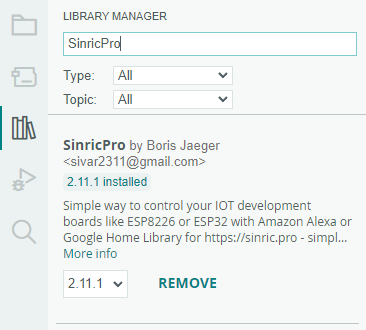
2.2 Código completo
// Uncomment the following line to enable serial debug output
//#define ENABLE_DEBUG

#ifdef ENABLE_DEBUG
    #define DEBUG_ESP_PORT Serial
    #define NODEBUG_WEBSOCKETS
    #define NDEBUG
#endif

#include <Arduino.h>
#if defined(ESP8266)
  #include <ESP8266WiFi.h>
#elif defined(ESP32) || defined(ARDUINO_ARCH_RP2040)
  #include <WiFi.h>
#endif

#include <SinricPro.h>
#include <SinricProLight.h>

#include <map>

#define WIFI_SSID  ""
#define WIFI_PASS  ""
#define APP_KEY    ""     // Should look like "de0bxxxx-1x3x-4x3x-ax2x-5dabxxxxxxxx"
#define APP_SECRET ""  // Should look like "5f36xxxx-x3x7-4x3x-xexe-e86724a9xxxx-4c4axxxx-3x3x-x5xe-x9x3-333d65xxxxxx"
#define LIGHT_ID   ""   // Should look like "5dc1564130xxxxxxxxxxxxxx"
#define BAUD_RATE  115200              // Change baudrate to your need for serial log

#define BLUE_PIN  27  // PIN for BLUE BC337 NPN transistor  - change this to your need (D5 = GPIO14 on ESP8266)
#define RED_PIN   14  // PIN for RED BC337 NPN transistor   - change this to your need (D6 = GPIO12 on ESP8266)
#define GREEN_PIN 12  // PIN for GREEN BC337 NPN transistor - change this to your need (D7 = GPIO13 on ESP8266)

struct Color {
    uint8_t r;
    uint8_t g;
    uint8_t b;
};

// Colortemperature lookup table
using ColorTemperatures = std::map<uint16_t, Color>;
ColorTemperatures colorTemperatures{
    //   {Temperature value, {color r, g, b}}
    {2000, {255, 138, 18}},
    {2200, {255, 147, 44}},
    {2700, {255, 169, 87}},
    {3000, {255, 180, 107}},
    {4000, {255, 209, 163}},
    {5000, {255, 228, 206}},
    {5500, {255, 236, 224}},
    {6000, {255, 243, 239}},
    {6500, {255, 249, 253}},
    {7000, {245, 243, 255}},
    {7500, {235, 238, 255}},
    {9000, {214, 225, 255}}};

struct DeviceState {                                   // Stores current device state with following initial values:
    bool  powerState       = false;                    // initial state is off
    Color color            = colorTemperatures[9000];  // color is set to white (9000k)
    int   colorTemperature = 9000;                     // color temperature is set to 9000k
    int   brightness       = 100;                      // brightness is set to 100
} device_state;

SinricProLight& myLight = SinricPro[LIGHT_ID];  // SinricProLight device

void setStripe() {
    int rValue = map(device_state.color.r * device_state.brightness, 0, 255 * 100, 0, 1023);  // calculate red value and map between 0 and 1023 for analogWrite
    int gValue = map(device_state.color.g * device_state.brightness, 0, 255 * 100, 0, 1023);  // calculate green value and map between 0 and 1023 for analogWrite
    int bValue = map(device_state.color.b * device_state.brightness, 0, 255 * 100, 0, 1023);  // calculate blue value and map between 0 and 1023 for analogWrite

    if (device_state.powerState == false) {  // turn off?
        analogWrite(RED_PIN, LOW);
        analogWrite(GREEN_PIN, LOW);
        analogWrite(BLUE_PIN, LOW);
    } else {
        analogWrite(RED_PIN, rValue);    // write red value to pin
        analogWrite(GREEN_PIN, gValue);  // write green value to pin
        analogWrite(BLUE_PIN, bValue);   // write blue value to pin
    }
}

bool onPowerState(const String& deviceId, bool& state) {
    device_state.powerState = state;  // store the new power state
    setStripe();                      // update the BC337 NPN transistors
    return true;
}

bool onBrightness(const String& deviceId, int& brightness) {
    device_state.brightness = brightness;  // store new brightness level
    setStripe();                           // update the BC337 NPN transistors
    return true;
}

bool onAdjustBrightness(const String& deviceId, int& brightnessDelta) {
    device_state.brightness += brightnessDelta;  // calculate and store new absolute brightness
    brightnessDelta = device_state.brightness;   // return absolute brightness
    setStripe();                                 // update the BC337 NPN transistors
    return true;
}

bool onColor(const String& deviceId, byte& r, byte& g, byte& b) {
    device_state.color.r = r;  // store new red value
    device_state.color.g = g;  // store new green value
    device_state.color.b = b;  // store new blue value
    setStripe();               // update the BC337 NPN transistors
    return true;
}

bool onColorTemperature(const String& deviceId, int& colorTemperature) {
    device_state.color            = colorTemperatures[colorTemperature];  // set rgb values from corresponding colortemperauture
    device_state.colorTemperature = colorTemperature;                     // store the current color temperature
    setStripe();                                                          // update the BC337 NPN transistors
    return true;
}

bool onIncreaseColorTemperature(const String& devceId, int& colorTemperature) {
    auto current = colorTemperatures.find(device_state.colorTemperature);  // get current entry from colorTemperature map
    auto next    = std::next(current);                                     // get next element
    if (next == colorTemperatures.end()) next = current;                   // prevent past last element
    device_state.color            = next->second;                          // set color
    device_state.colorTemperature = next->first;                           // set colorTemperature
    colorTemperature              = device_state.colorTemperature;         // return new colorTemperature
    setStripe();
    return true;
}

bool onDecreaseColorTemperature(const String& devceId, int& colorTemperature) {
    auto current = colorTemperatures.find(device_state.colorTemperature);  // get current entry from colorTemperature map
    auto next    = std::prev(current);                                     // get previous element
    if (next == colorTemperatures.end()) next = current;                   // prevent before first element
    device_state.color            = next->second;                          // set color
    device_state.colorTemperature = next->first;                           // set colorTemperature
    colorTemperature              = device_state.colorTemperature;         // return new colorTemperature
    setStripe();
    return true;
}

void setupWiFi() {
    Serial.printf("WiFi: connecting");

    #if defined(ESP8266)
        WiFi.setSleepMode(WIFI_NONE_SLEEP);
        WiFi.setAutoReconnect(true);
    #elif defined(ESP32)
        WiFi.setSleep(false);
        WiFi.setAutoReconnect(true);
    #endif

    WiFi.begin(WIFI_SSID, WIFI_PASS);

    while (WiFi.status() != WL_CONNECTED) {
        Serial.printf(".");
        delay(250);
    }
    Serial.printf("connected\r\nIP is %s\r\n", WiFi.localIP().toString().c_str());
}

void setupSinricPro() {
    myLight.onPowerState(onPowerState);                              // assign onPowerState callback
    myLight.onBrightness(onBrightness);                              // assign onBrightness callback
    myLight.onAdjustBrightness(onAdjustBrightness);                  // assign onAdjustBrightness callback
    myLight.onColor(onColor);                                        // assign onColor callback
    myLight.onColorTemperature(onColorTemperature);                  // assign onColorTemperature callback
    myLight.onDecreaseColorTemperature(onDecreaseColorTemperature);  // assign onDecreaseColorTemperature callback
    myLight.onIncreaseColorTemperature(onIncreaseColorTemperature);  // assign onIncreaseColorTemperature callback

    SinricPro.begin(APP_KEY, APP_SECRET);  // start SinricPro
}

void setup() {
    Serial.begin(BAUD_RATE);  // setup serial

    pinMode(RED_PIN, OUTPUT);    // set red-BC337 NPN transistor pin as output
    pinMode(GREEN_PIN, OUTPUT);  // set green-BC337 NPN transistor pin as output
    pinMode(BLUE_PIN, OUTPUT);   // set blue-BC337 NPN transistor pin as output

    setupWiFi();       // connect wifi
    setupSinricPro();  // setup SinricPro
}

void loop() {
    SinricPro.handle();  // handle SinricPro communication
}
Ver este código en GitHub Gist
Ahora también deberías poder controlarla con Alexa, GoogleHome y SmartThings.
Solución de problemas
-
Usa una fuente de alimentación que pueda suministrar suficiente corriente para la tira LED. Las tiras LED pueden consumir mucha corriente, así que es importante usar una fuente de alimentación capaz de cubrir las necesidades de la tira.
-
Consulta nuestra página de Solución de problemas para más detalles.
Tutoriales relacionados
- Cómo controlar un ESP32 o ESP8266 con Alexa y Google Home
- Interruptor regulable con un dimmer de luz AC RobotDyn
- Interruptor regulable con un módulo YYAC-3S
- Tutorial del interruptor, parte 1: encender y apagar un relé
Este documento es de código abierto. ¿Has visto una errata? Crea una issue