


Control a Relay with ESP32 or ESP8266 using Alexa and Google Home (Switch Tutorial Part 1)
In this section we’ll walk through creating a Sinric Pro Switch for ESP32, ESP8266 or Raspberry Pi Zero W and then control via Alexa, Google Home or SmartThings.
Prerequisites :
- ESP32, ESP8266 or RaspPi W x 1.
- SPDT Relay controller x 1.
- Jumper Wires.
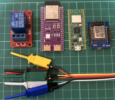
Quick introduction to Relay
A relay is an electrically operated switch that can be turned on or off by a low-voltage signal. It is like a regular switch in that it allows current to flow through or not, but it can be controlled by a much smaller voltage. This makes relays ideal for MCUs where it is necessary to control a high-voltage circuit with a low-voltage signal.
How it works
The operation of a relay can vary depending on the manufacturer, the wiring, and the type of relay controller being used. Some relay controllers require a high-level signal from the MCU to activate the relay, while others require a low-level signal. It is important to check the specifications of the relay controller before using it to ensure that it is compatible with your MCU.
High-level signal: A high-level signal is a signal that is above a certain voltage threshold. For example, a 5V relay controller may require a signal that is above 3.3V to activate the relay.
digitalWrite(pin, HIGH);
Low-level signal: A low-level signal is a signal that is below a certain voltage threshold. For example, a 5V relay controller may require a signal that is below 0.8V to activate the relay.
digitalWrite(pin, LOW);
High Voltage Connectors
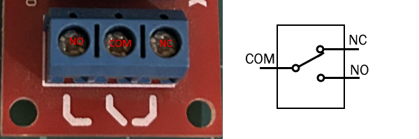
The relay module in the above has a single connector with three sockets: Common (COM), Normally Closed (NC), and Normally Open (NO).
Common (COM): COM is the common connection for both the NO and NC pins. Connect the high voltage device to the COM pin.
Normally Closed (NC): The circuit is closed by default.
Normally Open (NO): The circuit is open by default.
Normally open (NO) and normally closed (NC) contacts allow you to use one pin to control two separate circuits depending on your requirements. For example, you could use one pin to control the power to a light bulb and another pin to control the power to a motor. When the pin is high/low the light bulb will turn on otherwise the motor will turn on.
Wiring
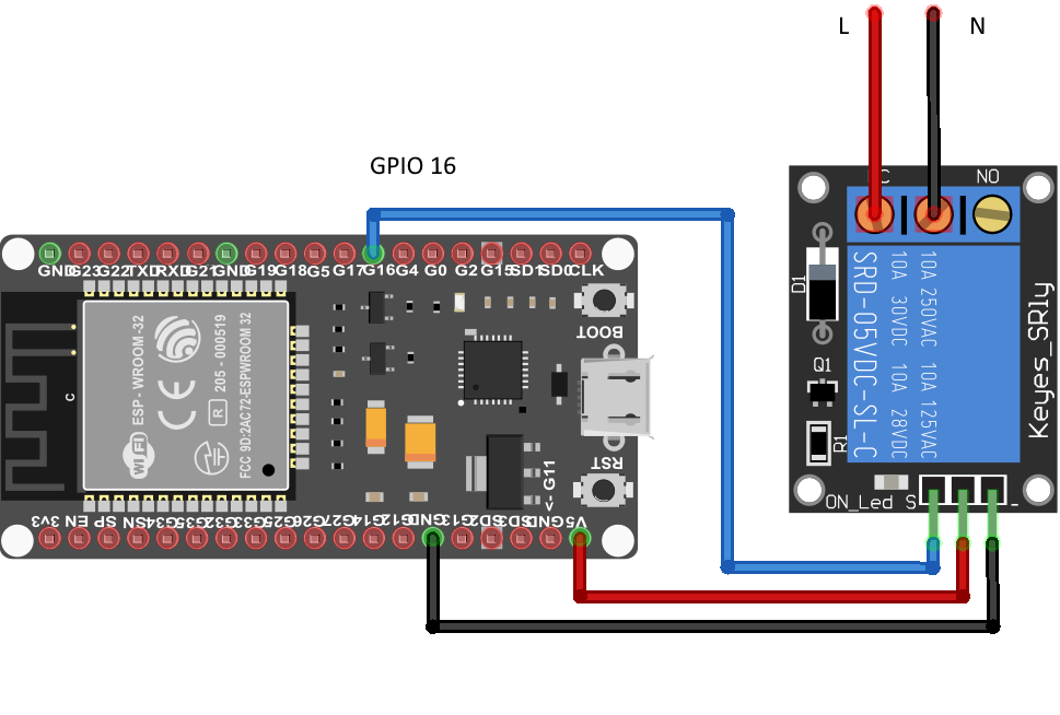
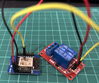
| MCU | Pin |
|---|---|
| ESP32 | 16 |
| ESP8266 | 12 (D6) |
| RaspPi W | 6 |
Before we integrate with Sinric Pro, it is important to verify that the relay is wired correctly. You can use the following code to check whether the relay turns on and off every 5 seconds.
#if defined(ESP8266)
  #define relay        12
#elif defined(ESP32)
  #define relay        16
#elif (ARDUINO_ARCH_RP2040)
  #define relay        6
#endif

void setup() {
  Serial.begin(115200);
  pinMode(relay, OUTPUT);
}

void loop() {
  Serial.println("Writing HIGH ..");
  digitalWrite(relay, HIGH);
  delay(5000);

  Serial.println("Writing LOW ..");
  digitalWrite(relay, LOW);
  delay(5000);
}
Step 1 : Create a new device in Sinric Pro
- Login to your Sinric Pro account, go to Devices menu on your left and click Add Device button (On top left).
- Enter the device name Switch, description My First Switch and select the device type as Switch.
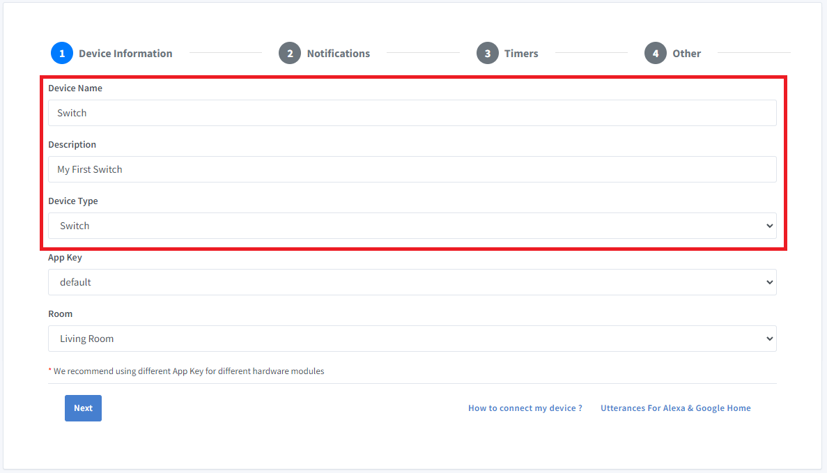
- Click Next the in the Notifications tab
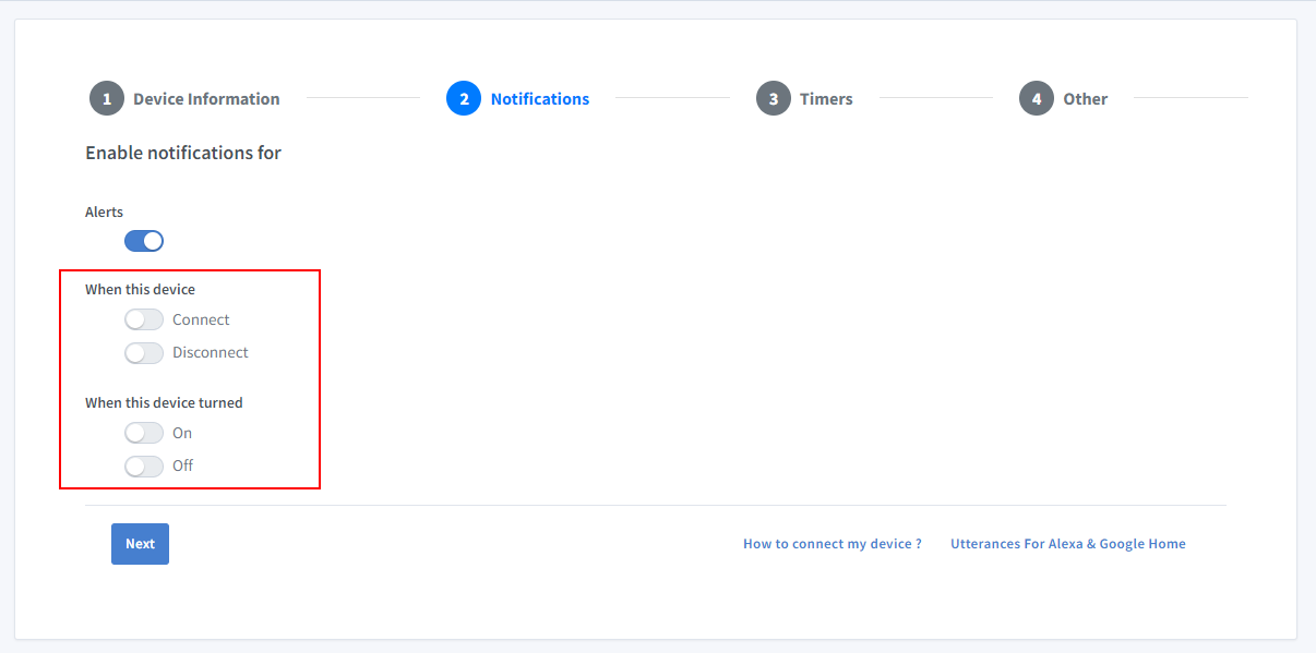
To receive push notifications when your device goes online or offline, enable the “Connect and Disconnect” option in the Sinric Pro app. To receive push notifications when your device turns on or off, enable the “On and Off” option.
-
Click Others and Click Save
-
Next screen will show the credentials required to connect the device you just created.
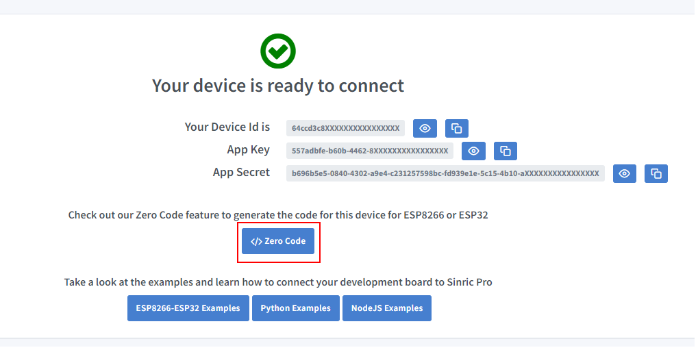
- Copy the Device Id, App Key and App Secret Keep these values secure. DO NOT SHARE THEM ON PUBLIC FORUMS !
Step 2 : Coding
2.1 Install Sinric Pro Library
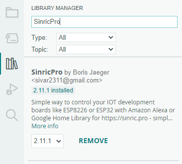
You can generate the code using Zero Code feature or write it by your self. If you do not have programming experice, we recommend to use Zero Code feature in the Portal to generate the code, download and flash.
2.2 Complete Code
#include <Arduino.h>
#if defined(ESP8266)
  #include <ESP8266WiFi.h>
#elif defined(ESP32) || defined(ARDUINO_ARCH_RP2040)
  #include <WiFi.h>
#endif

#include "SinricPro.h"
#include "SinricProSwitch.h"

#define WIFI_SSID         ""  // Change WIFI_SSID to your WiFi Name.
#define WIFI_PASS         ""  // Change WIFI_PASS to your WiFi password.
#define APP_KEY           ""  // Paste App Key from above
#define APP_SECRET        ""  // Paste App Secret from above
#define SWITCH_ID_1       ""  // Paste Device Id from  above

#if defined(ESP8266)
  #define RELAYPIN_1        12
#elif defined(ESP32)
  #define RELAYPIN_1        16
#elif (ARDUINO_ARCH_RP2040)
  #define RELAYPIN_1        6
#endif

#define BAUD_RATE         115200                // Change baudrate to your need

bool onPowerState1(const String &deviceId, bool &state) {
 Serial.printf("Device 1 turned %s", state?"on":"off");
 digitalWrite(RELAYPIN_1, state ? HIGH:LOW);

 /* If your relay is activated with low signal, change the above to below code
  digitalWrite(RELAYPIN_1, state ? LOW : HIGH); */

 return true; // request handled properly
}

// setup function for WiFi connection
void setupWiFi() {
  Serial.printf("\r\n[Wifi]: Connecting");

  #if defined(ESP8266)
    WiFi.setSleepMode(WIFI_NONE_SLEEP);
    WiFi.setAutoReconnect(true);
  #elif defined(ESP32)
    WiFi.setSleep(false);
    WiFi.setAutoReconnect(true);
  #endif

  WiFi.begin(WIFI_SSID, WIFI_PASS);

  while (WiFi.status() != WL_CONNECTED) {
    Serial.printf(".");
    delay(250);
  }

  Serial.printf("connected!\r\n[WiFi]: IP-Address is %s\r\n", WiFi.localIP().toString().c_str());
}

// setup function for SinricPro
void setupSinricPro() {
  // add devices and callbacks to SinricPro
  pinMode(RELAYPIN_1, OUTPUT);

  SinricProSwitch& mySwitch1 = SinricPro[SWITCH_ID_1];
  mySwitch1.onPowerState(onPowerState1);

  // setup SinricPro
  SinricPro.onConnected([](){ Serial.printf("Connected to SinricPro\r\n"); });
  SinricPro.onDisconnected([](){ Serial.printf("Disconnected from SinricPro\r\n"); });

  SinricPro.begin(APP_KEY, APP_SECRET);
}

// main setup function
void setup() {
  Serial.begin(BAUD_RATE); Serial.printf("\r\n\r\n");
  setupWiFi();
  setupSinricPro();
}

void loop() {
  SinricPro.handle();
}
Now you should be able to control the relay via Portal like in the below video.
Step 3 : Link Sinric Pro Alexa Skill with your account.
|
• Open your Amazon Alexa app. • Goto Skills & Games. • Search for Sinric Pro. • Click ENABLE TO USE. • Enter your Sinric Pro credentails in linking page. • Ask Alexa to discover new devices. • Ask Alexa to turn on the Switch |
Step 4 : Link Sinric Pro Google Home action with your account.
|
• Open Google Home and click on Add. • Select Setup Device • Select Works with Google Home • Search for Sinric Pro. • Link your account. • Discover new devices • Ask Google Home to turn on the Switch |
Step 5 : Link Sinric Pro SmartThings with your account.
|
• Open the SmartThings app and tap the + Icon • Select Device • Select Sinric Pro under By Brand • Link your account. • Now you can turn on or off Switch from the dashboard |
Continue to Part 2 of this article series to learn how to add a push button to toggle the relay.
Troubleshooting
Please refer to our Troubleshooting page for possible solutions to your issue.
Related tutorials
- How to control an ESP32 or ESP8266 with Alexa and Google Home
- Switch tutorial part 2: toggle the relay with a button
- Switch tutorial part 3: multiple relays and buttons
- Relay with MicroPython on ESP32
- Dimmable switch with a RobotDyn AC light dimmer
This document is open source. See a typo? Please create an issue