


Control a 5050 RGB LED Strip with ESP32 or ESP8266 using Alexa and Google Home
In this section we’ll walk through creating a LED Light Strip using ESP32, ESP8266 and then control it via Amazon Alexa, Google Home or SmartThings.
Prerequisites :
- ESP32, ESP8266 x 1.
- IRF540N MOSFET, STP16nF06L MOSFET, S8050 NPN transistor or BC337 NPN transistor x 3
- 1k resistor x 3
- Jumper Wires.
In this tutorial we are going to use BC337 NPN transistors.
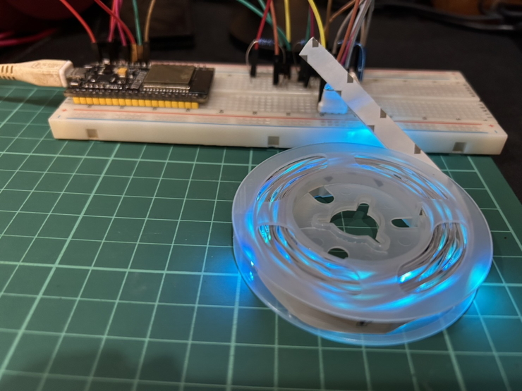
Quick introduction to 5050 LED strips
5050 LED strips are a type of LED strip that is made up of individual LEDs that are grouped together in sets of three. Each set of three LEDs is known as a pixel. The pixels are arranged in a long, thin strip, and they can be cut to length to fit your needs. 5050 LED strips are available in a variety of colors, including red, green, blue, white, and yellow. They can also be purchased in different brightness levels. 5050 LED strips are affordable LED strips that look similar to more expensive Neopixel strips. However, the LEDs in 5050 LED strips cannot be controlled individually. This means that you can only use one color for the entire strip at a time.
Here is a table that summarizes the key differences between 5050 LED strips and Neopixel strips:
| Feature | 5050 LED strips | Neopixel strips |
|---|---|---|
| Price | Affordable | More expensive |
| Individually addressable LEDs | No | Yes |
| Animations | Limited to common animations such as color changing and dimming | Complex animations with individual LEDs are possible |
5050 RGB LED strip pinout
A standard (non-addressable) 5050 RGB strip has 4 pads: one shared positive pad and one pad for each colour.
| Pad | Function |
|---|---|
+ (+5V or +12V) |
Common positive (common anode). Connect to the power supply |
R |
Red channel, switched to ground |
G |
Green channel, switched to ground |
B |
Blue channel, switched to ground |
- The strip is common anode: a colour lights up when its pad is pulled to ground. This is why each colour is driven through a transistor or MOSFET, and not directly from a GPIO.
- The order of the pads is not the same on every strip (for example
+ G R Bor+ R G B). Read the labels printed on the strip next to the pads. - Check the voltage printed on the strip. 5V and 12V strips look the same.
- “5050” is the size of each LED package: 5.0 mm x 5.0 mm. Each package contains a red, a green and a blue LED.
Wiring
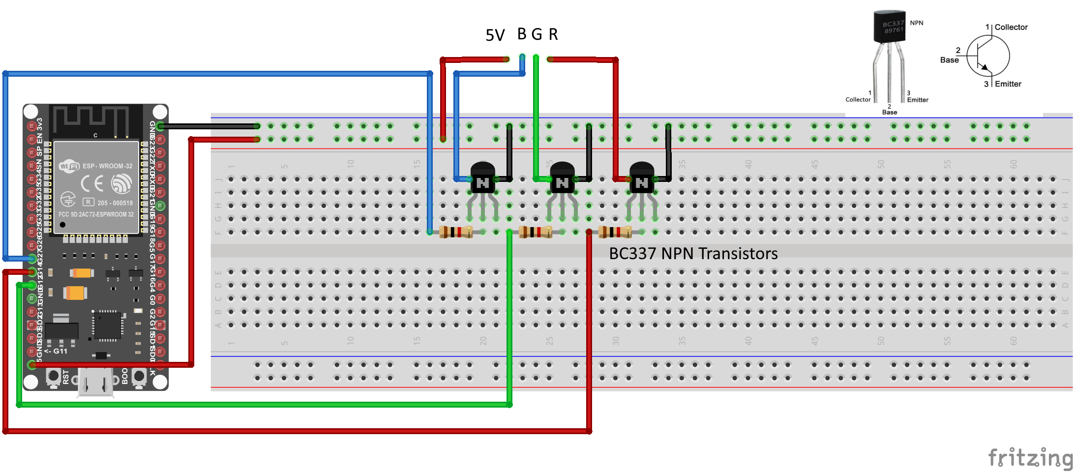
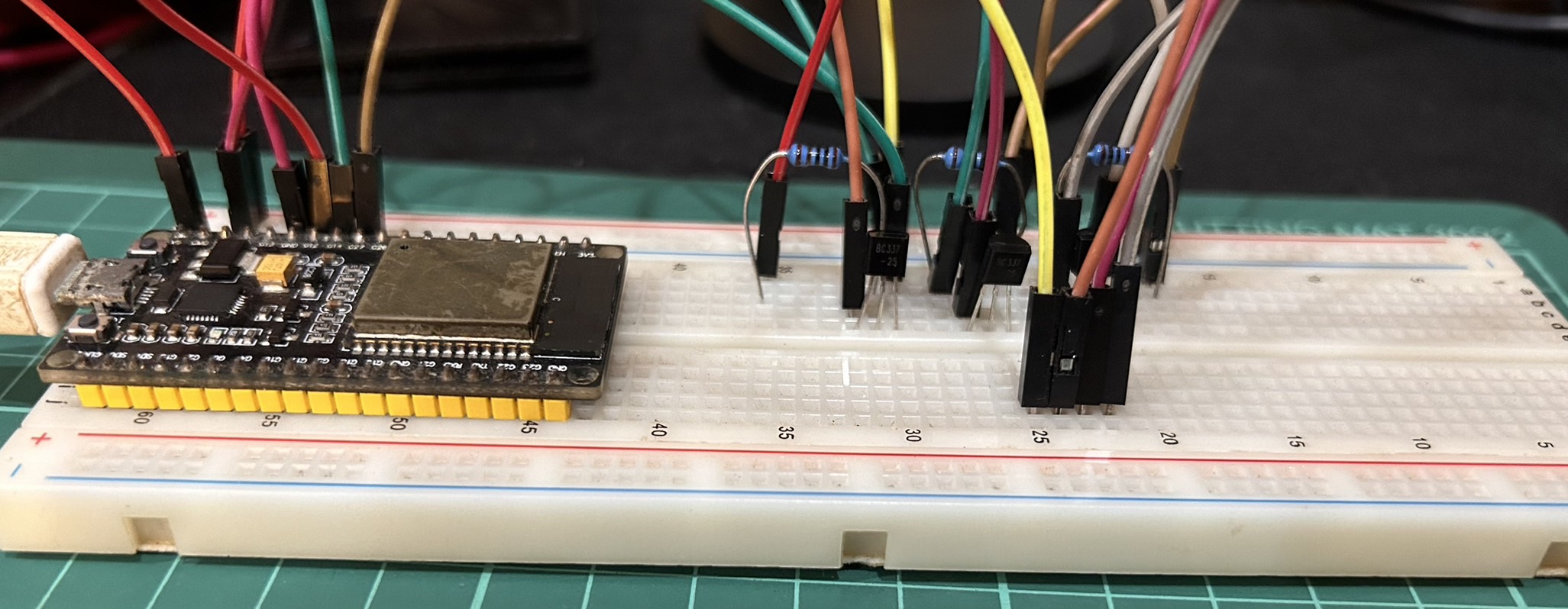
| Strip | ESP32 PIN |
|---|---|
| 5V | 5V |
| R | 14 |
| G | 12 |
| B | 27 |
Let’s verify LED Strip is wired correctly and working.
// Red, green, and blue pins for PWM control
const int ledR = 14;
const int ledG = 12;
const int bluePin = 27;

uint8_t color = 0;          // a value from 0 to 255 representing the hue
uint32_t R, G, B;           // the Red Green and Blue color components
uint8_t brightness = 255;  // 255 is maximum brightness, but can be changed.  Might need 256 for common anode to fully turn off.
bool invert = false;

void hueToRGB(uint8_t hue, uint8_t brightness);

void setup() {
  Serial.begin(115200);
  delay(10);

  ledcAttachPin(ledR, 1);
  ledcAttachPin(ledG, 2);
  ledcAttachPin(ledB, 3);

  // Initialize channels
  // channels 0-15, resolution 1-16 bits, freq limits depend on resolution
  // ledcSetup(uint8_t channel, uint32_t freq, uint8_t resolution_bits);
  ledcSetup(1, 12000, 8); // 12 kHz PWM, 8-bit resolution
  ledcSetup(2, 12000, 8);
  ledcSetup(3, 12000, 8);
}

void loop(){
   for (color = 0; color < 255; color++) { // Slew through the color spectrum
    hueToRGB(color, brightness);  // call function to convert hue to RGB

    // write the RGB values to the pins
    ledcWrite(1, R); // write red component to channel 1, etc.
    ledcWrite(2, G);
    ledcWrite(3, B);

    delay(100); // full cycle of rgb over 256 colors takes 26 seconds
 }
}

// Courtesy http://www.instructables.com/id/How-to-Use-an-RGB-LED/?ALLSTEPS
// function to convert a color to its Red, Green, and Blue components.

void hueToRGB(uint8_t hue, uint8_t brightness) {
    uint16_t scaledHue = (hue * 6);
    uint8_t segment = scaledHue / 256; // segment 0 to 5 around the
                                            // color wheel
    uint16_t segmentOffset =
      scaledHue - (segment * 256); // position within the segment

    uint8_t complement = 0;
    uint16_t prev = (brightness * ( 255 -  segmentOffset)) / 256;
    uint16_t next = (brightness *  segmentOffset) / 256;

    if(invert)
    {
      brightness = 255 - brightness;
      complement = 255;
      prev = 255 - prev;
      next = 255 - next;
    }

    switch(segment ) {
    case 0:      // red
        R = brightness;
        G = next;
        B = complement;
    break;
    case 1:     // yellow
        R = prev;
        G = brightness;
        B = complement;
    break;
    case 2:     // green
        R = complement;
        G = brightness;
        B = next;
    break;
    case 3:    // cyan
        R = complement;
        G = prev;
        B = brightness;
    break;
    case 4:    // blue
        R = next;
        G = complement;
        B = brightness;
    break;
   case 5:      // magenta
    default:
        R = brightness;
        G = complement;
        B = prev;
    break;
    }
}
LED Strip will change the colors like this:
Step 1 : Create a new device in Sinric Pro
- Login to your Sinric Pro account, go to Devices menu on your left and click Add Device button (On top left).
- Enter the device name LED strip, description My LED strip and select the device type as Smart Light Bulb.
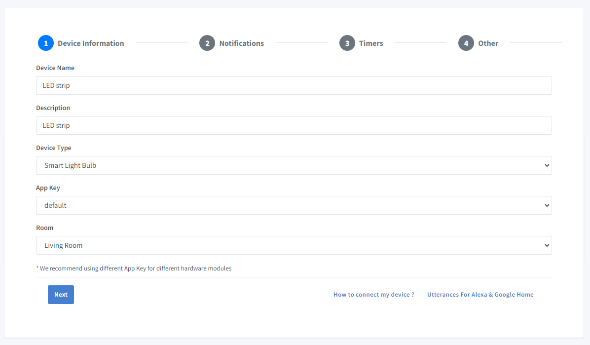
-
Click Next the in the Notifications tab
-
Click Others tab and Click Save
-
Next screen will show the credentials required to connect the device you just created.
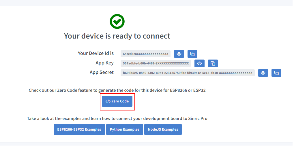
- Copy the Device Id, App Key and App Secret Keep these values secure. DO NOT SHARE THEM ON PUBLIC FORUMS !
Step 2 : Connect to Sinric Pro
Step 2.1 Install Sinric Pro Library
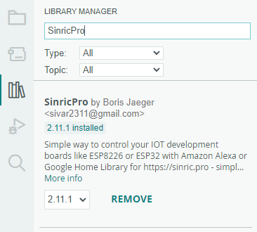
2.2 Complete Code
// Uncomment the following line to enable serial debug output
//#define ENABLE_DEBUG

#ifdef ENABLE_DEBUG
    #define DEBUG_ESP_PORT Serial
    #define NODEBUG_WEBSOCKETS
    #define NDEBUG
#endif

#include <Arduino.h>
#if defined(ESP8266)
  #include <ESP8266WiFi.h>
#elif defined(ESP32) || defined(ARDUINO_ARCH_RP2040)
  #include <WiFi.h>
#endif

#include <SinricPro.h>
#include <SinricProLight.h>

#include <map>

#define WIFI_SSID  ""
#define WIFI_PASS  ""
#define APP_KEY    ""     // Should look like "de0bxxxx-1x3x-4x3x-ax2x-5dabxxxxxxxx"
#define APP_SECRET ""  // Should look like "5f36xxxx-x3x7-4x3x-xexe-e86724a9xxxx-4c4axxxx-3x3x-x5xe-x9x3-333d65xxxxxx"
#define LIGHT_ID   ""   // Should look like "5dc1564130xxxxxxxxxxxxxx"
#define BAUD_RATE  115200              // Change baudrate to your need for serial log

#define BLUE_PIN  27  // PIN for BLUE BC337 NPN transistor  - change this to your need (D5 = GPIO14 on ESP8266)
#define RED_PIN   14  // PIN for RED BC337 NPN transistor   - change this to your need (D6 = GPIO12 on ESP8266)
#define GREEN_PIN 12  // PIN for GREEN BC337 NPN transistor - change this to your need (D7 = GPIO13 on ESP8266)

struct Color {
    uint8_t r;
    uint8_t g;
    uint8_t b;
};

// Colortemperature lookup table
using ColorTemperatures = std::map<uint16_t, Color>;
ColorTemperatures colorTemperatures{
    //   {Temperature value, {color r, g, b}}
    {2000, {255, 138, 18}},
    {2200, {255, 147, 44}},
    {2700, {255, 169, 87}},
    {3000, {255, 180, 107}},
    {4000, {255, 209, 163}},
    {5000, {255, 228, 206}},
    {5500, {255, 236, 224}},
    {6000, {255, 243, 239}},
    {6500, {255, 249, 253}},
    {7000, {245, 243, 255}},
    {7500, {235, 238, 255}},
    {9000, {214, 225, 255}}};

struct DeviceState {                                   // Stores current device state with following initial values:
    bool  powerState       = false;                    // initial state is off
    Color color            = colorTemperatures[9000];  // color is set to white (9000k)
    int   colorTemperature = 9000;                     // color temperature is set to 9000k
    int   brightness       = 100;                      // brightness is set to 100
} device_state;

SinricProLight& myLight = SinricPro[LIGHT_ID];  // SinricProLight device

void setStripe() {
    int rValue = map(device_state.color.r * device_state.brightness, 0, 255 * 100, 0, 1023);  // calculate red value and map between 0 and 1023 for analogWrite
    int gValue = map(device_state.color.g * device_state.brightness, 0, 255 * 100, 0, 1023);  // calculate green value and map between 0 and 1023 for analogWrite
    int bValue = map(device_state.color.b * device_state.brightness, 0, 255 * 100, 0, 1023);  // calculate blue value and map between 0 and 1023 for analogWrite

    if (device_state.powerState == false) {  // turn off?
        analogWrite(RED_PIN, LOW);
        analogWrite(GREEN_PIN, LOW);
        analogWrite(BLUE_PIN, LOW);
    } else {
        analogWrite(RED_PIN, rValue);    // write red value to pin
        analogWrite(GREEN_PIN, gValue);  // write green value to pin
        analogWrite(BLUE_PIN, bValue);   // write blue value to pin
    }
}

bool onPowerState(const String& deviceId, bool& state) {
    device_state.powerState = state;  // store the new power state
    setStripe();                      // update the BC337 NPN transistors
    return true;
}

bool onBrightness(const String& deviceId, int& brightness) {
    device_state.brightness = brightness;  // store new brightness level
    setStripe();                           // update the BC337 NPN transistors
    return true;
}

bool onAdjustBrightness(const String& deviceId, int& brightnessDelta) {
    device_state.brightness += brightnessDelta;  // calculate and store new absolute brightness
    brightnessDelta = device_state.brightness;   // return absolute brightness
    setStripe();                                 // update the BC337 NPN transistors
    return true;
}

bool onColor(const String& deviceId, byte& r, byte& g, byte& b) {
    device_state.color.r = r;  // store new red value
    device_state.color.g = g;  // store new green value
    device_state.color.b = b;  // store new blue value
    setStripe();               // update the BC337 NPN transistors
    return true;
}

bool onColorTemperature(const String& deviceId, int& colorTemperature) {
    device_state.color            = colorTemperatures[colorTemperature];  // set rgb values from corresponding colortemperauture
    device_state.colorTemperature = colorTemperature;                     // store the current color temperature
    setStripe();                                                          // update the BC337 NPN transistors
    return true;
}

bool onIncreaseColorTemperature(const String& devceId, int& colorTemperature) {
    auto current = colorTemperatures.find(device_state.colorTemperature);  // get current entry from colorTemperature map
    auto next    = std::next(current);                                     // get next element
    if (next == colorTemperatures.end()) next = current;                   // prevent past last element
    device_state.color            = next->second;                          // set color
    device_state.colorTemperature = next->first;                           // set colorTemperature
    colorTemperature              = device_state.colorTemperature;         // return new colorTemperature
    setStripe();
    return true;
}

bool onDecreaseColorTemperature(const String& devceId, int& colorTemperature) {
    auto current = colorTemperatures.find(device_state.colorTemperature);  // get current entry from colorTemperature map
    auto next    = std::prev(current);                                     // get previous element
    if (next == colorTemperatures.end()) next = current;                   // prevent before first element
    device_state.color            = next->second;                          // set color
    device_state.colorTemperature = next->first;                           // set colorTemperature
    colorTemperature              = device_state.colorTemperature;         // return new colorTemperature
    setStripe();
    return true;
}

void setupWiFi() {
    Serial.printf("WiFi: connecting");

    #if defined(ESP8266)
        WiFi.setSleepMode(WIFI_NONE_SLEEP);
        WiFi.setAutoReconnect(true);
    #elif defined(ESP32)
        WiFi.setSleep(false);
        WiFi.setAutoReconnect(true);
    #endif

    WiFi.begin(WIFI_SSID, WIFI_PASS);

    while (WiFi.status() != WL_CONNECTED) {
        Serial.printf(".");
        delay(250);
    }
    Serial.printf("connected\r\nIP is %s\r\n", WiFi.localIP().toString().c_str());
}

void setupSinricPro() {
    myLight.onPowerState(onPowerState);                              // assign onPowerState callback
    myLight.onBrightness(onBrightness);                              // assign onBrightness callback
    myLight.onAdjustBrightness(onAdjustBrightness);                  // assign onAdjustBrightness callback
    myLight.onColor(onColor);                                        // assign onColor callback
    myLight.onColorTemperature(onColorTemperature);                  // assign onColorTemperature callback
    myLight.onDecreaseColorTemperature(onDecreaseColorTemperature);  // assign onDecreaseColorTemperature callback
    myLight.onIncreaseColorTemperature(onIncreaseColorTemperature);  // assign onIncreaseColorTemperature callback

    SinricPro.begin(APP_KEY, APP_SECRET);  // start SinricPro
}

void setup() {
    Serial.begin(BAUD_RATE);  // setup serial

    pinMode(RED_PIN, OUTPUT);    // set red-BC337 NPN transistor pin as output
    pinMode(GREEN_PIN, OUTPUT);  // set green-BC337 NPN transistor pin as output
    pinMode(BLUE_PIN, OUTPUT);   // set blue-BC337 NPN transistor pin as output

    setupWiFi();       // connect wifi
    setupSinricPro();  // setup SinricPro
}

void loop() {
    SinricPro.handle();  // handle SinricPro communication
}
Now you should be able to control via Alexa, GoogleHome and SmartThings as well.
Troubleshooting
-
Use a power supply that can provide enough current for the LED strip. LED strips can consume a lot of current, so it is important to use a power supply that can provide enough current to meet the needs of the strip.
-
Please refer to our Troubleshooting page for more details.
Related tutorials
- How to control an ESP32 or ESP8266 with Alexa and Google Home
- Dimmable switch with a RobotDyn AC light dimmer
- Dimmable switch with a YYAC-3S module
- Switch tutorial part 1: turn a relay on and off
This document is open source. See a typo? Please create an issue