


Controle uma Fita LED RGB 5050 com ESP32 ou ESP8266 usando Alexa e Google Home
Nesta seção vamos criar uma Fita LED usando ESP32, ESP8266 e depois controlá-la via Amazon Alexa, Google Home ou SmartThings.
Pré-requisitos:
- ESP32, ESP8266 x 1.
- MOSFET IRF540N, MOSFET STP16nF06L, transistor NPN S8050 ou transistor NPN BC337 x 3
- Resistor de 1k x 3
- Cabos Jumper.
Neste tutorial vamos usar transistores NPN BC337.
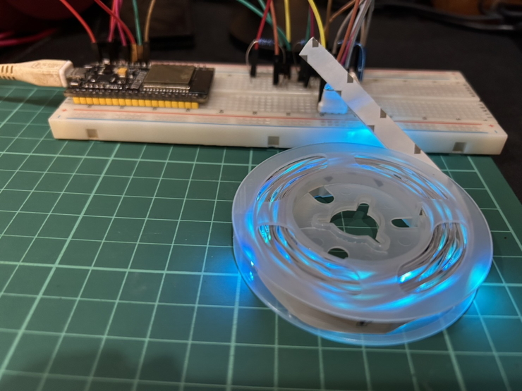
Introdução rápida às fitas LED 5050
As fitas LED 5050 são um tipo de fita LED feita de LEDs individuais que são agrupados em conjuntos de três. Cada conjunto de três LEDs é conhecido como um pixel. Os pixels são organizados em uma fita longa e fina, e podem ser cortados no comprimento para atender às suas necessidades. As fitas LED 5050 estão disponíveis em uma variedade de cores, incluindo vermelho, verde, azul, branco e amarelo. Elas também podem ser compradas em diferentes níveis de brilho. As fitas LED 5050 são fitas LED acessíveis que parecem similares às fitas Neopixel mais caras. No entanto, os LEDs nas fitas LED 5050 não podem ser controlados individualmente. Isso significa que você só pode usar uma cor para toda a fita por vez.
Aqui está uma tabela que resume as principais diferenças entre fitas LED 5050 e fitas Neopixel:
| Característica | Fitas LED 5050 | Fitas Neopixel |
|---|---|---|
| Preço | Acessível | Mais caro |
| LEDs endereçáveis individualmente | Não | Sim |
| Animações | Limitado a animações comuns como mudança de cor e dimmer | Animações complexas com LEDs individuais são possíveis |
Pinagem da fita LED RGB 5050
Uma fita RGB 5050 comum (não endereçável) tem 4 contatos: um positivo compartilhado e um para cada cor.
| Contato | Função |
|---|---|
+ (+5V ou +12V) |
Positivo comum (anodo comum). Conecte à fonte de alimentação |
R |
Canal vermelho, chaveado para o terra |
G |
Canal verde, chaveado para o terra |
B |
Canal azul, chaveado para o terra |
- A fita é de anodo comum: uma cor acende quando o contato dela é levado ao terra. Por isso cada cor é acionada por um transistor ou MOSFET, e não diretamente por um GPIO.
- A ordem dos contatos não é a mesma em todas as fitas (por exemplo
+ G R Bou+ R G B). Leia as marcações impressas na fita ao lado dos contatos. - Confira a tensão impressa na fita. Fitas de 5V e de 12V têm a mesma aparência.
- “5050” é o tamanho de cada encapsulamento de LED: 5,0 mm x 5,0 mm. Cada encapsulamento contém um LED vermelho, um verde e um azul.
Fiação
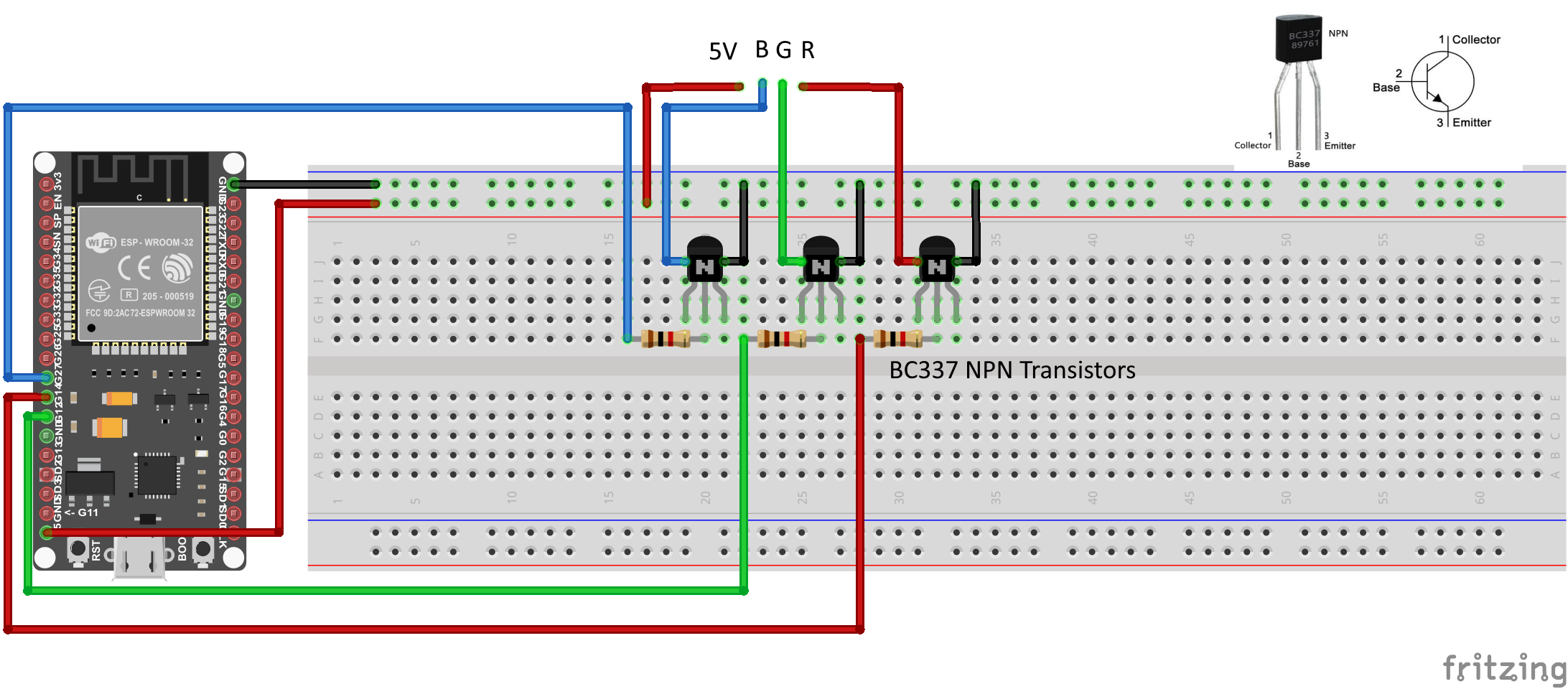
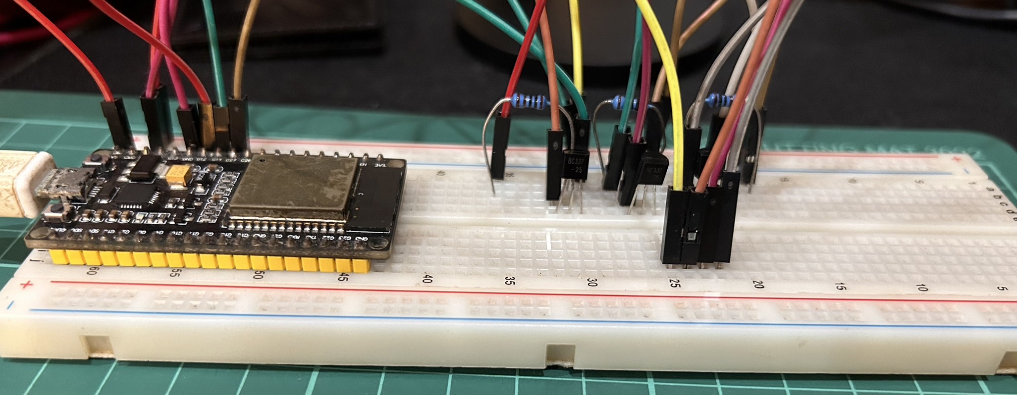
| Fita | PINO ESP32 |
|---|---|
| 5V | 5V |
| R | 14 |
| G | 12 |
| B | 27 |
Vamos verificar se a Fita LED está conectada corretamente e funcionando.
// Red, green, and blue pins for PWM control
const int ledR = 14;
const int ledG = 12;
const int bluePin = 27;

uint8_t color = 0;          // a value from 0 to 255 representing the hue
uint32_t R, G, B;           // the Red Green and Blue color components
uint8_t brightness = 255;  // 255 is maximum brightness, but can be changed.  Might need 256 for common anode to fully turn off.
bool invert = false;

void hueToRGB(uint8_t hue, uint8_t brightness);

void setup() {
  Serial.begin(115200);
  delay(10);

  ledcAttachPin(ledR, 1);
  ledcAttachPin(ledG, 2);
  ledcAttachPin(ledB, 3);

  // Initialize channels
  // channels 0-15, resolution 1-16 bits, freq limits depend on resolution
  // ledcSetup(uint8_t channel, uint32_t freq, uint8_t resolution_bits);
  ledcSetup(1, 12000, 8); // 12 kHz PWM, 8-bit resolution
  ledcSetup(2, 12000, 8);
  ledcSetup(3, 12000, 8);
}

void loop(){
   for (color = 0; color < 255; color++) { // Slew through the color spectrum
    hueToRGB(color, brightness);  // call function to convert hue to RGB

    // write the RGB values to the pins
    ledcWrite(1, R); // write red component to channel 1, etc.
    ledcWrite(2, G);
    ledcWrite(3, B);

    delay(100); // full cycle of rgb over 256 colors takes 26 seconds
 }
}

// Courtesy http://www.instructables.com/id/How-to-Use-an-RGB-LED/?ALLSTEPS
// function to convert a color to its Red, Green, and Blue components.

void hueToRGB(uint8_t hue, uint8_t brightness) {
    uint16_t scaledHue = (hue * 6);
    uint8_t segment = scaledHue / 256; // segment 0 to 5 around the
                                            // color wheel
    uint16_t segmentOffset =
      scaledHue - (segment * 256); // position within the segment

    uint8_t complement = 0;
    uint16_t prev = (brightness * ( 255 -  segmentOffset)) / 256;
    uint16_t next = (brightness *  segmentOffset) / 256;

    if(invert)
    {
      brightness = 255 - brightness;
      complement = 255;
      prev = 255 - prev;
      next = 255 - next;
    }

    switch(segment ) {
    case 0:      // red
        R = brightness;
        G = next;
        B = complement;
    break;
    case 1:     // yellow
        R = prev;
        G = brightness;
        B = complement;
    break;
    case 2:     // green
        R = complement;
        G = brightness;
        B = next;
    break;
    case 3:    // cyan
        R = complement;
        G = prev;
        B = brightness;
    break;
    case 4:    // blue
        R = next;
        G = complement;
        B = brightness;
    break;
   case 5:      // magenta
    default:
        R = brightness;
        G = complement;
        B = prev;
    break;
    }
}
A Fita LED mudará as cores assim:
Passo 1: Criar um novo dispositivo no Sinric Pro
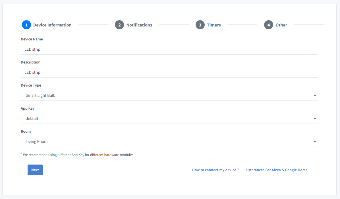
- Faça login na sua conta Sinric Pro, vá ao menu Dispositivos à esquerda e clique no botão Adicionar Dispositivo (no canto superior esquerdo).
- Digite o nome do dispositivo Fita LED, descrição Minha Fita LED e selecione o tipo de dispositivo como Smart Light Bulb.
-
Clique em Próximo na aba Notificações
-
Clique na aba Outros e Clique em Salvar
-
A próxima tela mostrará as credenciais necessárias para conectar o dispositivo que você acabou de criar.
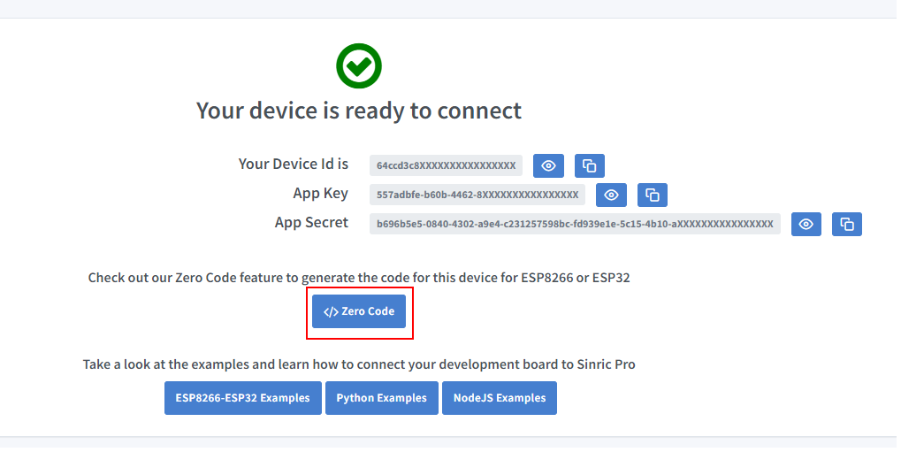
- Copie o ID do Dispositivo, Chave do App e Segredo do App Mantenha esses valores seguros. NÃO OS COMPARTILHE EM FÓRUNS PÚBLICOS!
Passo 2: Conectar ao Sinric Pro
Passo 2.1 Instalar a Biblioteca Sinric Pro
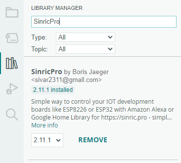
2.2 Código Completo
// Uncomment the following line to enable serial debug output
//#define ENABLE_DEBUG

#ifdef ENABLE_DEBUG
    #define DEBUG_ESP_PORT Serial
    #define NODEBUG_WEBSOCKETS
    #define NDEBUG
#endif

#include <Arduino.h>
#if defined(ESP8266)
  #include <ESP8266WiFi.h>
#elif defined(ESP32) || defined(ARDUINO_ARCH_RP2040)
  #include <WiFi.h>
#endif

#include <SinricPro.h>
#include <SinricProLight.h>

#include <map>

#define WIFI_SSID  ""
#define WIFI_PASS  ""
#define APP_KEY    ""     // Should look like "de0bxxxx-1x3x-4x3x-ax2x-5dabxxxxxxxx"
#define APP_SECRET ""  // Should look like "5f36xxxx-x3x7-4x3x-xexe-e86724a9xxxx-4c4axxxx-3x3x-x5xe-x9x3-333d65xxxxxx"
#define LIGHT_ID   ""   // Should look like "5dc1564130xxxxxxxxxxxxxx"
#define BAUD_RATE  115200              // Change baudrate to your need for serial log

#define BLUE_PIN  27  // PIN for BLUE BC337 NPN transistor  - change this to your need (D5 = GPIO14 on ESP8266)
#define RED_PIN   14  // PIN for RED BC337 NPN transistor   - change this to your need (D6 = GPIO12 on ESP8266)
#define GREEN_PIN 12  // PIN for GREEN BC337 NPN transistor - change this to your need (D7 = GPIO13 on ESP8266)

struct Color {
    uint8_t r;
    uint8_t g;
    uint8_t b;
};

// Colortemperature lookup table
using ColorTemperatures = std::map<uint16_t, Color>;
ColorTemperatures colorTemperatures{
    //   {Temperature value, {color r, g, b}}
    {2000, {255, 138, 18}},
    {2200, {255, 147, 44}},
    {2700, {255, 169, 87}},
    {3000, {255, 180, 107}},
    {4000, {255, 209, 163}},
    {5000, {255, 228, 206}},
    {5500, {255, 236, 224}},
    {6000, {255, 243, 239}},
    {6500, {255, 249, 253}},
    {7000, {245, 243, 255}},
    {7500, {235, 238, 255}},
    {9000, {214, 225, 255}}};

struct DeviceState {                                   // Stores current device state with following initial values:
    bool  powerState       = false;                    // initial state is off
    Color color            = colorTemperatures[9000];  // color is set to white (9000k)
    int   colorTemperature = 9000;                     // color temperature is set to 9000k
    int   brightness       = 100;                      // brightness is set to 100
} device_state;

SinricProLight& myLight = SinricPro[LIGHT_ID];  // SinricProLight device

void setStripe() {
    int rValue = map(device_state.color.r * device_state.brightness, 0, 255 * 100, 0, 1023);  // calculate red value and map between 0 and 1023 for analogWrite
    int gValue = map(device_state.color.g * device_state.brightness, 0, 255 * 100, 0, 1023);  // calculate green value and map between 0 and 1023 for analogWrite
    int bValue = map(device_state.color.b * device_state.brightness, 0, 255 * 100, 0, 1023);  // calculate blue value and map between 0 and 1023 for analogWrite

    if (device_state.powerState == false) {  // turn off?
        analogWrite(RED_PIN, LOW);
        analogWrite(GREEN_PIN, LOW);
        analogWrite(BLUE_PIN, LOW);
    } else {
        analogWrite(RED_PIN, rValue);    // write red value to pin
        analogWrite(GREEN_PIN, gValue);  // write green value to pin
        analogWrite(BLUE_PIN, bValue);   // write blue value to pin
    }
}

bool onPowerState(const String& deviceId, bool& state) {
    device_state.powerState = state;  // store the new power state
    setStripe();                      // update the BC337 NPN transistors
    return true;
}

bool onBrightness(const String& deviceId, int& brightness) {
    device_state.brightness = brightness;  // store new brightness level
    setStripe();                           // update the BC337 NPN transistors
    return true;
}

bool onAdjustBrightness(const String& deviceId, int& brightnessDelta) {
    device_state.brightness += brightnessDelta;  // calculate and store new absolute brightness
    brightnessDelta = device_state.brightness;   // return absolute brightness
    setStripe();                                 // update the BC337 NPN transistors
    return true;
}

bool onColor(const String& deviceId, byte& r, byte& g, byte& b) {
    device_state.color.r = r;  // store new red value
    device_state.color.g = g;  // store new green value
    device_state.color.b = b;  // store new blue value
    setStripe();               // update the BC337 NPN transistors
    return true;
}

bool onColorTemperature(const String& deviceId, int& colorTemperature) {
    device_state.color            = colorTemperatures[colorTemperature];  // set rgb values from corresponding colortemperauture
    device_state.colorTemperature = colorTemperature;                     // store the current color temperature
    setStripe();                                                          // update the BC337 NPN transistors
    return true;
}

bool onIncreaseColorTemperature(const String& devceId, int& colorTemperature) {
    auto current = colorTemperatures.find(device_state.colorTemperature);  // get current entry from colorTemperature map
    auto next    = std::next(current);                                     // get next element
    if (next == colorTemperatures.end()) next = current;                   // prevent past last element
    device_state.color            = next->second;                          // set color
    device_state.colorTemperature = next->first;                           // set colorTemperature
    colorTemperature              = device_state.colorTemperature;         // return new colorTemperature
    setStripe();
    return true;
}

bool onDecreaseColorTemperature(const String& devceId, int& colorTemperature) {
    auto current = colorTemperatures.find(device_state.colorTemperature);  // get current entry from colorTemperature map
    auto next    = std::prev(current);                                     // get previous element
    if (next == colorTemperatures.end()) next = current;                   // prevent before first element
    device_state.color            = next->second;                          // set color
    device_state.colorTemperature = next->first;                           // set colorTemperature
    colorTemperature              = device_state.colorTemperature;         // return new colorTemperature
    setStripe();
    return true;
}

void setupWiFi() {
    Serial.printf("WiFi: connecting");

    #if defined(ESP8266)
        WiFi.setSleepMode(WIFI_NONE_SLEEP);
        WiFi.setAutoReconnect(true);
    #elif defined(ESP32)
        WiFi.setSleep(false);
        WiFi.setAutoReconnect(true);
    #endif

    WiFi.begin(WIFI_SSID, WIFI_PASS);

    while (WiFi.status() != WL_CONNECTED) {
        Serial.printf(".");
        delay(250);
    }
    Serial.printf("connected\r\nIP is %s\r\n", WiFi.localIP().toString().c_str());
}

void setupSinricPro() {
    myLight.onPowerState(onPowerState);                              // assign onPowerState callback
    myLight.onBrightness(onBrightness);                              // assign onBrightness callback
    myLight.onAdjustBrightness(onAdjustBrightness);                  // assign onAdjustBrightness callback
    myLight.onColor(onColor);                                        // assign onColor callback
    myLight.onColorTemperature(onColorTemperature);                  // assign onColorTemperature callback
    myLight.onDecreaseColorTemperature(onDecreaseColorTemperature);  // assign onDecreaseColorTemperature callback
    myLight.onIncreaseColorTemperature(onIncreaseColorTemperature);  // assign onIncreaseColorTemperature callback

    SinricPro.begin(APP_KEY, APP_SECRET);  // start SinricPro
}

void setup() {
    Serial.begin(BAUD_RATE);  // setup serial

    pinMode(RED_PIN, OUTPUT);    // set red-BC337 NPN transistor pin as output
    pinMode(GREEN_PIN, OUTPUT);  // set green-BC337 NPN transistor pin as output
    pinMode(BLUE_PIN, OUTPUT);   // set blue-BC337 NPN transistor pin as output

    setupWiFi();       // connect wifi
    setupSinricPro();  // setup SinricPro
}

void loop() {
    SinricPro.handle();  // handle SinricPro communication
}
Agora você deve conseguir controlar via Alexa, GoogleHome e SmartThings também.
Solução de Problemas
-
Use uma fonte de alimentação que pode fornecer corrente suficiente para a fita LED. As fitas LED podem consumir muita corrente, então é importante usar uma fonte de alimentação que possa fornecer corrente suficiente para atender às necessidades da fita.
-
Consulte nossa página de Solução de Problemas para mais detalhes.
Este documento é código aberto. Viu um erro de digitação? Por favor, crie uma issue