


Add a Push Button to an ESP32 or ESP8266 Relay with Alexa (Switch Tutorial Part 2)
In this section, we will continue from Part 1 and add a push button to turn on and off the relay. We will also update the new status of the relay on the Sinric Pro server.
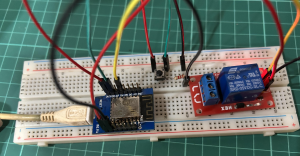
Prerequisites :
| Component | Quantity |
|---|---|
| ESP32, ESP8266 or RaspPi W | 1 |
| SPDT Relay controller | 1 |
| Push button | 1 |
| 10K ohm resistor | 1 |
| Jumper Wires | 1 |
Quick introduction to Push button & debouncing
Push buttons can often generate false signals when pressed. This is because the mechanical switch that makes up the button can bounce or chatter slightly when it is pressed. This can cause the button to send multiple signals to the MCU, even though it was only pressed once. The process of eliminating the these signals generated is called debouncing. To eliminate the noise of the push button, we can record a state change and then ignore further input for a few milliseconds.
Wiring
There are two ways you can wire a push button.
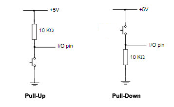
Pull-Up - When the switch is pressed, digitalRead reads LOW (0) signal.
Pull-Down - When the switch is pressed, digitalRead reads HIGH (1) signal.
| MCU | Pin | Component |
|---|---|---|
| ESP32 | 16 | Relay |
| ESP32 | 17 | Button |
| ESP8266 | 12 (D6) | Relay |
| ESP8266 | 15 (D8) | Button |
| RaspPi W | 6 | Relay |
| RaspPi W | 7 | Button |
Before we integrate with sketch from part 1, it is important to verify that the button is wired correctly and working. You can use the following code to check whether the button press.
We are going to use Pull-Down method to wire our push button.
#if defined(ESP8266)
  #define BUTTON_PIN        12
#elif defined(ESP32)
  #define BUTTON_PIN        16
#elif (ARDUINO_ARCH_RP2040)
  #define BUTTON_PIN        6
#endif

int button_state;
int lastbutton_state = LOW;

unsigned long last_debounce_time = 0;
unsigned long debounce_delay = 50; // increase if needed.

void setup() {
  Serial.begin(115200);
  pinMode(BUTTON_PIN, INPUT);
}

void handle_button_press() {
  int reading = digitalRead(BUTTON_PIN);
  if (reading != lastbutton_state) {
    last_debounce_time = millis();
  }

  if ((millis() - last_debounce_time) > debounce_delay) {
    if (reading != button_state) {
      button_state = reading;

      if (button_state == HIGH) {
        Serial.printf("Pressed!\r\n");
      }
    }
  }

  lastbutton_state = reading;
}

void loop() {
  handle_button_press();
}
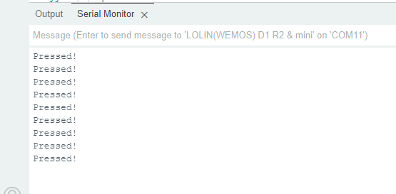
Now let’s complete sketch with push button, Relay controller with Sinric Pro integration.
#include <Arduino.h>
#if defined(ESP8266)
  #include <ESP8266WiFi.h>
#elif defined(ESP32) || defined(ARDUINO_ARCH_RP2040)
  #include <WiFi.h>
#endif

#include "SinricPro.h"
#include "SinricProSwitch.h"

#define WIFI_SSID         ""  // Change WIFI_SSID to your WiFi Name.
#define WIFI_PASS         ""  // Change WIFI_PASS to your WiFi password.
#define APP_KEY           ""  // App Key
#define APP_SECRET        ""  // App Secret
#define SWITCH_ID_1       ""  // Device Id

#define BAUD_RATE         115200              // Change baudrate to your need

#if defined(ESP8266)
  #define BUTTON_PIN        15
  #define RELAYPIN_1        12
#elif defined(ESP32)
  #define BUTTON_PIN        17
  #define RELAYPIN_1        16
#elif (ARDUINO_ARCH_RP2040)
  #define BUTTON_PIN        7
  #define RELAYPIN_1        6
#endif

bool myPowerState = false;
unsigned long lastBtnPress = 0;

bool onPowerState(const String &deviceId, bool &state) {
  Serial.printf("Device %s turned %s (via SinricPro) \r\n", deviceId.c_str(), state?"on":"off");

  digitalWrite(RELAYPIN_1, state ? HIGH:LOW);

   /* If your relay is activated with low signal, change the above to below code
  digitalWrite(RELAYPIN_1, state ? LOW : HIGH); */

  myPowerState = state;
  return true; // request handled properly
}

void handleButtonPress() {
  unsigned long actualMillis = millis();
  if (digitalRead(BUTTON_PIN) == HIGH && actualMillis - lastBtnPress > 1000)  {
    if (myPowerState) {
      myPowerState = false;
    } else {
      myPowerState = true;
    }

    // get Switch device back
    SinricProSwitch& mySwitch = SinricPro[SWITCH_ID_1];

    // send powerstate event to server
    mySwitch.sendPowerStateEvent(myPowerState); // send the new powerState to SinricPro server
    Serial.printf("Device %s turned %s (manually via button)\r\n", mySwitch.getDeviceId().c_str(), myPowerState?"on":"off");

    // set relay status
    digitalWrite(RELAYPIN_1, myPowerState ? HIGH:LOW);

    lastBtnPress = actualMillis;  // update last button press variable
  }
}

// setup function for WiFi connection
void setupWiFi() {
  Serial.printf("\r\n[Wifi]: Connecting");

  #if defined(ESP8266)
    WiFi.setSleepMode(WIFI_NONE_SLEEP);
    WiFi.setAutoReconnect(true);
  #elif defined(ESP32)
    WiFi.setSleep(false);
    WiFi.setAutoReconnect(true);
  #endif

  WiFi.begin(WIFI_SSID, WIFI_PASS);

  while (WiFi.status() != WL_CONNECTED) {
    Serial.printf(".");
    delay(250);
  }
  Serial.printf("connected!\r\n[WiFi]: IP-Address is %s\r\n", WiFi.localIP().toString().c_str());
}

// setup function for SinricPro
void setupSinricPro() {
  // add device to SinricPro
  SinricProSwitch& mySwitch = SinricPro[SWITCH_ID_1];

  // set callback function to device
  mySwitch.onPowerState(onPowerState);

  // setup SinricPro
  SinricPro.onConnected([](){ Serial.printf("Connected to SinricPro\r\n"); });
  SinricPro.onDisconnected([](){ Serial.printf("Disconnected from SinricPro\r\n"); });
  SinricPro.begin(APP_KEY, APP_SECRET);
}


void setup() {
  pinMode(BUTTON_PIN, INPUT);
  pinMode(RELAYPIN_1, OUTPUT);

  Serial.begin(BAUD_RATE); Serial.printf("\r\n\r\n");
  setupWiFi();
  setupSinricPro();
}

void loop() {
  handleButtonPress();
  SinricPro.handle();
}
Continue to Part 3 of this article series to learn how to control multiple push buttons with multiple relays.
Troubleshooting
Please refer to our Troubleshooting page for possible solutions to your issue.
Related tutorials
- How to control an ESP32 or ESP8266 with Alexa and Google Home
- Switch tutorial part 1: turn a relay on and off
- Switch tutorial part 3: multiple relays and buttons
- Smart button
This document is open source. See a typo? Please create an issue