


Controllare una striscia LED RGB 5050 con ESP32 o ESP8266 tramite Alexa e Google Home
In questa sezione vedremo come realizzare una striscia luminosa a LED con ESP32 o ESP8266 e come controllarla poi tramite Amazon Alexa, Google Home o SmartThings.
Prerequisiti :
- ESP32, ESP8266 x 1.
- MOSFET IRF540N, MOSFET STP16nF06L, transistor NPN S8050 o transistor NPN BC337 x 3
- Resistenza da 1k x 3
- Cavetti jumper.
In questo tutorial useremo transistor NPN BC337.
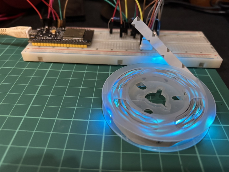
Breve introduzione alle strisce LED 5050
Le strisce LED 5050 sono un tipo di striscia LED composta da singoli LED raggruppati a tre a tre. Ogni gruppo di tre LED è detto pixel. I pixel sono disposti su una striscia lunga e sottile, che puoi tagliare alla lunghezza che ti serve. Le strisce LED 5050 sono disponibili in vari colori, tra cui rosso, verde, blu, bianco e giallo. Si possono acquistare anche con diversi livelli di luminosità. Le strisce LED 5050 sono strisce economiche dall’aspetto simile alle più costose strisce Neopixel. Tuttavia, i LED delle strisce 5050 non si possono controllare singolarmente. Questo significa che puoi usare un solo colore alla volta per l’intera striscia.
Ecco una tabella che riassume le principali differenze tra le strisce LED 5050 e le strisce Neopixel:
| Caratteristica | Strisce LED 5050 | Strisce Neopixel |
|---|---|---|
| Prezzo | Economico | Più costoso |
| LED indirizzabili singolarmente | No | Sì |
| Animazioni | Limitate alle animazioni più comuni, come cambio colore e regolazione della luminosità | Sono possibili animazioni complesse con i singoli LED |
Piedinatura della striscia LED RGB 5050
Una striscia RGB 5050 standard (non indirizzabile) ha 4 piazzole: una piazzola positiva comune e una piazzola per ogni colore.
| Piazzola | Funzione |
|---|---|
+ (+5V o +12V) |
Positivo comune (anodo comune). Collegalo all’alimentatore |
R |
Canale rosso, commutato verso massa |
G |
Canale verde, commutato verso massa |
B |
Canale blu, commutato verso massa |
- La striscia è ad anodo comune: un colore si accende quando la sua piazzola viene portata a massa. Per questo ogni colore viene pilotato tramite un transistor o un MOSFET, e non direttamente da un GPIO.
- L’ordine delle piazzole non è lo stesso su tutte le strisce (ad esempio
+ G R Boppure+ R G B). Leggi le etichette stampate sulla striscia accanto alle piazzole. - Controlla la tensione stampata sulla striscia. Le strisce a 5V e a 12V hanno lo stesso aspetto.
- “5050” indica le dimensioni del package di ogni LED: 5,0 mm x 5,0 mm. Ogni package contiene un LED rosso, uno verde e uno blu.
Cablaggio
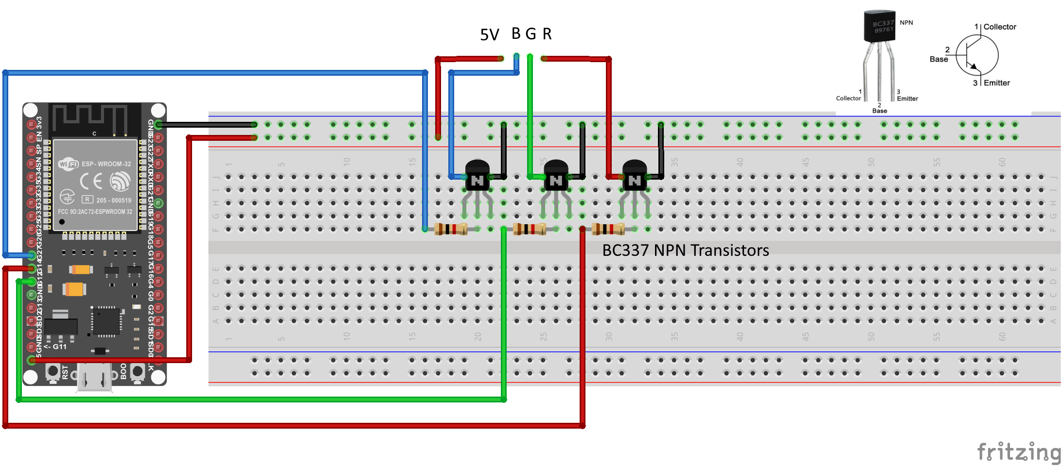
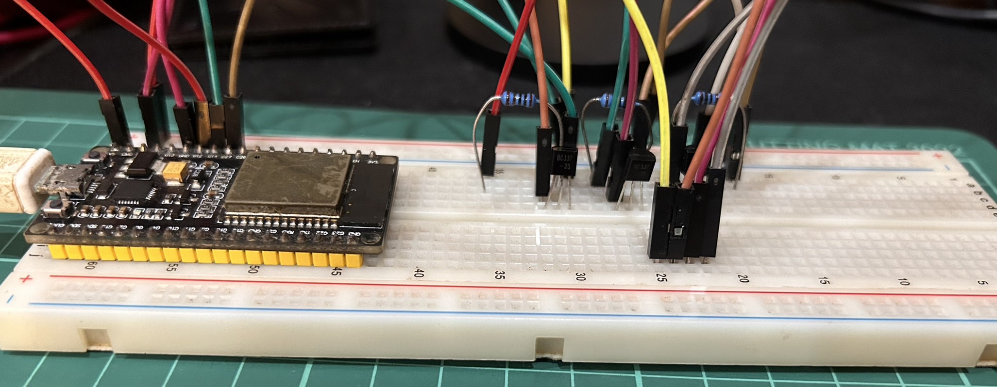
| Striscia | PIN ESP32 |
|---|---|
| 5V | 5V |
| R | 14 |
| G | 12 |
| B | 27 |
Verifichiamo che la striscia LED sia cablata correttamente e funzioni.
// Red, green, and blue pins for PWM control
const int ledR = 14;
const int ledG = 12;
const int bluePin = 27;

uint8_t color = 0;          // a value from 0 to 255 representing the hue
uint32_t R, G, B;           // the Red Green and Blue color components
uint8_t brightness = 255;  // 255 is maximum brightness, but can be changed.  Might need 256 for common anode to fully turn off.
bool invert = false;

void hueToRGB(uint8_t hue, uint8_t brightness);

void setup() {
  Serial.begin(115200);
  delay(10);

  ledcAttachPin(ledR, 1);
  ledcAttachPin(ledG, 2);
  ledcAttachPin(ledB, 3);

  // Initialize channels
  // channels 0-15, resolution 1-16 bits, freq limits depend on resolution
  // ledcSetup(uint8_t channel, uint32_t freq, uint8_t resolution_bits);
  ledcSetup(1, 12000, 8); // 12 kHz PWM, 8-bit resolution
  ledcSetup(2, 12000, 8);
  ledcSetup(3, 12000, 8);
}

void loop(){
   for (color = 0; color < 255; color++) { // Slew through the color spectrum
    hueToRGB(color, brightness);  // call function to convert hue to RGB

    // write the RGB values to the pins
    ledcWrite(1, R); // write red component to channel 1, etc.
    ledcWrite(2, G);
    ledcWrite(3, B);

    delay(100); // full cycle of rgb over 256 colors takes 26 seconds
 }
}

// Courtesy http://www.instructables.com/id/How-to-Use-an-RGB-LED/?ALLSTEPS
// function to convert a color to its Red, Green, and Blue components.

void hueToRGB(uint8_t hue, uint8_t brightness) {
    uint16_t scaledHue = (hue * 6);
    uint8_t segment = scaledHue / 256; // segment 0 to 5 around the
                                            // color wheel
    uint16_t segmentOffset =
      scaledHue - (segment * 256); // position within the segment

    uint8_t complement = 0;
    uint16_t prev = (brightness * ( 255 -  segmentOffset)) / 256;
    uint16_t next = (brightness *  segmentOffset) / 256;

    if(invert)
    {
      brightness = 255 - brightness;
      complement = 255;
      prev = 255 - prev;
      next = 255 - next;
    }

    switch(segment ) {
    case 0:      // red
        R = brightness;
        G = next;
        B = complement;
    break;
    case 1:     // yellow
        R = prev;
        G = brightness;
        B = complement;
    break;
    case 2:     // green
        R = complement;
        G = brightness;
        B = next;
    break;
    case 3:    // cyan
        R = complement;
        G = prev;
        B = brightness;
    break;
    case 4:    // blue
        R = next;
        G = complement;
        B = brightness;
    break;
   case 5:      // magenta
    default:
        R = brightness;
        G = complement;
        B = prev;
    break;
    }
}
Vedi questo codice su GitHub Gist
La striscia LED cambierà colore in questo modo:
Passo 1 : Crea un nuovo dispositivo in Sinric Pro
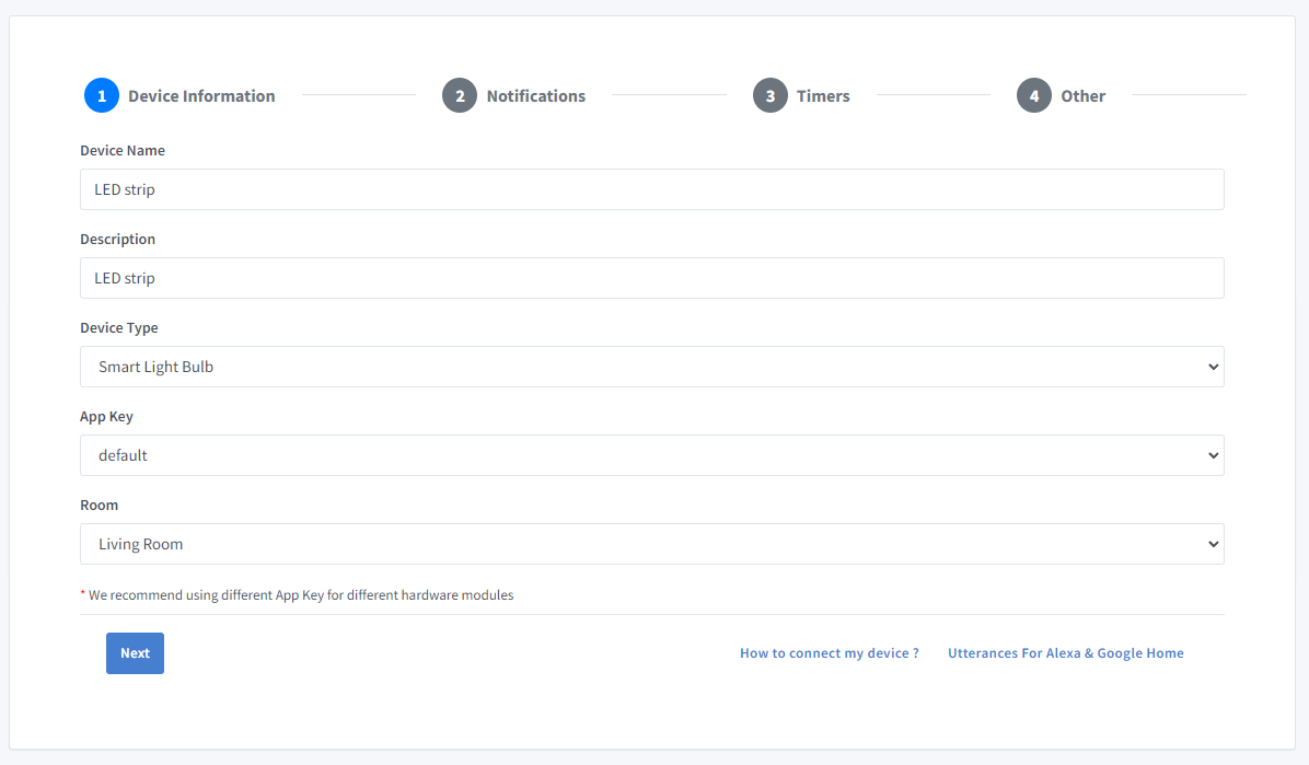
- Accedi al tuo account Sinric Pro, apri il menu Devices a sinistra e fai clic sul pulsante Add Device (in alto a sinistra).
- Inserisci il nome del dispositivo LED strip, la descrizione My LED strip e seleziona il tipo di dispositivo Smart Light Bulb.
-
Fai clic su Next nella scheda Notifications
-
Apri la scheda Others e fai clic su Save
-
La schermata successiva mostra le credenziali necessarie per collegare il dispositivo appena creato.
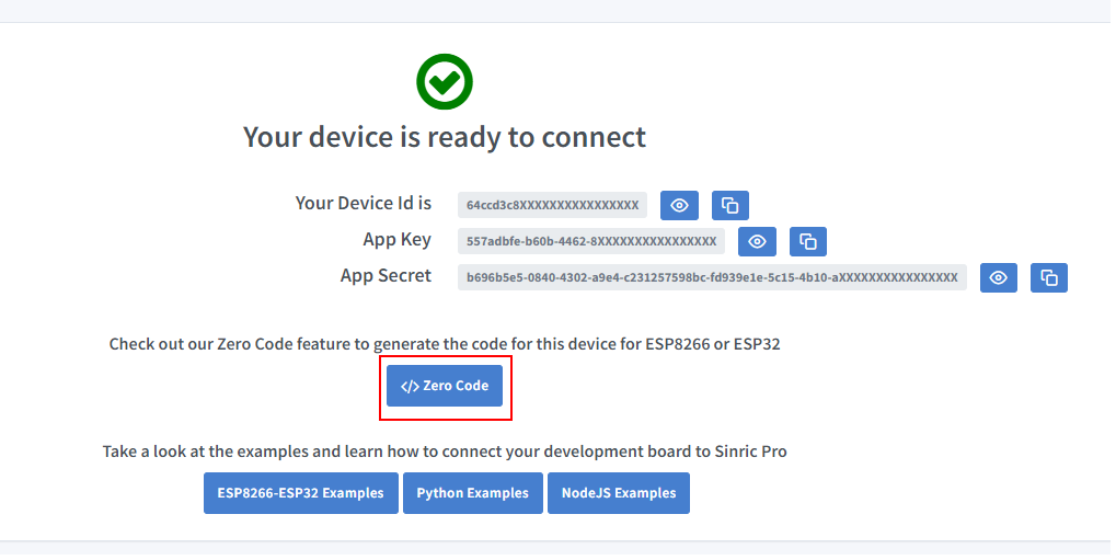
- Copia Device Id, App Key e App Secret Tieni questi valori al sicuro. NON CONDIVIDERLI SU FORUM PUBBLICI !
Passo 2 : Collegati a Sinric Pro
Passo 2.1 Installa la libreria Sinric Pro
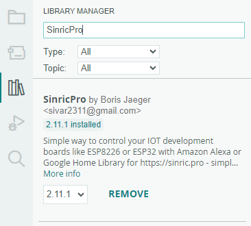
2.2 Codice completo
// Uncomment the following line to enable serial debug output
//#define ENABLE_DEBUG

#ifdef ENABLE_DEBUG
    #define DEBUG_ESP_PORT Serial
    #define NODEBUG_WEBSOCKETS
    #define NDEBUG
#endif

#include <Arduino.h>
#if defined(ESP8266)
  #include <ESP8266WiFi.h>
#elif defined(ESP32) || defined(ARDUINO_ARCH_RP2040)
  #include <WiFi.h>
#endif

#include <SinricPro.h>
#include <SinricProLight.h>

#include <map>

#define WIFI_SSID  ""
#define WIFI_PASS  ""
#define APP_KEY    ""     // Should look like "de0bxxxx-1x3x-4x3x-ax2x-5dabxxxxxxxx"
#define APP_SECRET ""  // Should look like "5f36xxxx-x3x7-4x3x-xexe-e86724a9xxxx-4c4axxxx-3x3x-x5xe-x9x3-333d65xxxxxx"
#define LIGHT_ID   ""   // Should look like "5dc1564130xxxxxxxxxxxxxx"
#define BAUD_RATE  115200              // Change baudrate to your need for serial log

#define BLUE_PIN  27  // PIN for BLUE BC337 NPN transistor  - change this to your need (D5 = GPIO14 on ESP8266)
#define RED_PIN   14  // PIN for RED BC337 NPN transistor   - change this to your need (D6 = GPIO12 on ESP8266)
#define GREEN_PIN 12  // PIN for GREEN BC337 NPN transistor - change this to your need (D7 = GPIO13 on ESP8266)

struct Color {
    uint8_t r;
    uint8_t g;
    uint8_t b;
};

// Colortemperature lookup table
using ColorTemperatures = std::map<uint16_t, Color>;
ColorTemperatures colorTemperatures{
    //   {Temperature value, {color r, g, b}}
    {2000, {255, 138, 18}},
    {2200, {255, 147, 44}},
    {2700, {255, 169, 87}},
    {3000, {255, 180, 107}},
    {4000, {255, 209, 163}},
    {5000, {255, 228, 206}},
    {5500, {255, 236, 224}},
    {6000, {255, 243, 239}},
    {6500, {255, 249, 253}},
    {7000, {245, 243, 255}},
    {7500, {235, 238, 255}},
    {9000, {214, 225, 255}}};

struct DeviceState {                                   // Stores current device state with following initial values:
    bool  powerState       = false;                    // initial state is off
    Color color            = colorTemperatures[9000];  // color is set to white (9000k)
    int   colorTemperature = 9000;                     // color temperature is set to 9000k
    int   brightness       = 100;                      // brightness is set to 100
} device_state;

SinricProLight& myLight = SinricPro[LIGHT_ID];  // SinricProLight device

void setStripe() {
    int rValue = map(device_state.color.r * device_state.brightness, 0, 255 * 100, 0, 1023);  // calculate red value and map between 0 and 1023 for analogWrite
    int gValue = map(device_state.color.g * device_state.brightness, 0, 255 * 100, 0, 1023);  // calculate green value and map between 0 and 1023 for analogWrite
    int bValue = map(device_state.color.b * device_state.brightness, 0, 255 * 100, 0, 1023);  // calculate blue value and map between 0 and 1023 for analogWrite

    if (device_state.powerState == false) {  // turn off?
        analogWrite(RED_PIN, LOW);
        analogWrite(GREEN_PIN, LOW);
        analogWrite(BLUE_PIN, LOW);
    } else {
        analogWrite(RED_PIN, rValue);    // write red value to pin
        analogWrite(GREEN_PIN, gValue);  // write green value to pin
        analogWrite(BLUE_PIN, bValue);   // write blue value to pin
    }
}

bool onPowerState(const String& deviceId, bool& state) {
    device_state.powerState = state;  // store the new power state
    setStripe();                      // update the BC337 NPN transistors
    return true;
}

bool onBrightness(const String& deviceId, int& brightness) {
    device_state.brightness = brightness;  // store new brightness level
    setStripe();                           // update the BC337 NPN transistors
    return true;
}

bool onAdjustBrightness(const String& deviceId, int& brightnessDelta) {
    device_state.brightness += brightnessDelta;  // calculate and store new absolute brightness
    brightnessDelta = device_state.brightness;   // return absolute brightness
    setStripe();                                 // update the BC337 NPN transistors
    return true;
}

bool onColor(const String& deviceId, byte& r, byte& g, byte& b) {
    device_state.color.r = r;  // store new red value
    device_state.color.g = g;  // store new green value
    device_state.color.b = b;  // store new blue value
    setStripe();               // update the BC337 NPN transistors
    return true;
}

bool onColorTemperature(const String& deviceId, int& colorTemperature) {
    device_state.color            = colorTemperatures[colorTemperature];  // set rgb values from corresponding colortemperauture
    device_state.colorTemperature = colorTemperature;                     // store the current color temperature
    setStripe();                                                          // update the BC337 NPN transistors
    return true;
}

bool onIncreaseColorTemperature(const String& devceId, int& colorTemperature) {
    auto current = colorTemperatures.find(device_state.colorTemperature);  // get current entry from colorTemperature map
    auto next    = std::next(current);                                     // get next element
    if (next == colorTemperatures.end()) next = current;                   // prevent past last element
    device_state.color            = next->second;                          // set color
    device_state.colorTemperature = next->first;                           // set colorTemperature
    colorTemperature              = device_state.colorTemperature;         // return new colorTemperature
    setStripe();
    return true;
}

bool onDecreaseColorTemperature(const String& devceId, int& colorTemperature) {
    auto current = colorTemperatures.find(device_state.colorTemperature);  // get current entry from colorTemperature map
    auto next    = std::prev(current);                                     // get previous element
    if (next == colorTemperatures.end()) next = current;                   // prevent before first element
    device_state.color            = next->second;                          // set color
    device_state.colorTemperature = next->first;                           // set colorTemperature
    colorTemperature              = device_state.colorTemperature;         // return new colorTemperature
    setStripe();
    return true;
}

void setupWiFi() {
    Serial.printf("WiFi: connecting");

    #if defined(ESP8266)
        WiFi.setSleepMode(WIFI_NONE_SLEEP);
        WiFi.setAutoReconnect(true);
    #elif defined(ESP32)
        WiFi.setSleep(false);
        WiFi.setAutoReconnect(true);
    #endif

    WiFi.begin(WIFI_SSID, WIFI_PASS);

    while (WiFi.status() != WL_CONNECTED) {
        Serial.printf(".");
        delay(250);
    }
    Serial.printf("connected\r\nIP is %s\r\n", WiFi.localIP().toString().c_str());
}

void setupSinricPro() {
    myLight.onPowerState(onPowerState);                              // assign onPowerState callback
    myLight.onBrightness(onBrightness);                              // assign onBrightness callback
    myLight.onAdjustBrightness(onAdjustBrightness);                  // assign onAdjustBrightness callback
    myLight.onColor(onColor);                                        // assign onColor callback
    myLight.onColorTemperature(onColorTemperature);                  // assign onColorTemperature callback
    myLight.onDecreaseColorTemperature(onDecreaseColorTemperature);  // assign onDecreaseColorTemperature callback
    myLight.onIncreaseColorTemperature(onIncreaseColorTemperature);  // assign onIncreaseColorTemperature callback

    SinricPro.begin(APP_KEY, APP_SECRET);  // start SinricPro
}

void setup() {
    Serial.begin(BAUD_RATE);  // setup serial

    pinMode(RED_PIN, OUTPUT);    // set red-BC337 NPN transistor pin as output
    pinMode(GREEN_PIN, OUTPUT);  // set green-BC337 NPN transistor pin as output
    pinMode(BLUE_PIN, OUTPUT);   // set blue-BC337 NPN transistor pin as output

    setupWiFi();       // connect wifi
    setupSinricPro();  // setup SinricPro
}

void loop() {
    SinricPro.handle();  // handle SinricPro communication
}
Vedi questo codice su GitHub Gist
Ora dovresti riuscire a controllarla anche tramite Alexa, Google Home e SmartThings.
Risoluzione dei problemi
-
Usa un alimentatore in grado di fornire corrente sufficiente per la striscia LED. Le strisce LED possono assorbire molta corrente, quindi è importante usare un alimentatore che fornisca abbastanza corrente per le esigenze della striscia.
-
Per maggiori dettagli consulta la nostra pagina Risoluzione dei problemi.
Tutorial correlati
- Come controllare un ESP32 o ESP8266 con Alexa e Google Home
- Interruttore dimmerabile con un dimmer AC RobotDyn
- Interruttore dimmerabile con un modulo YYAC-3S
- Tutorial Switch parte 1: accendere e spegnere un relè
Questo documento è open source. Hai trovato un errore di battitura? Crea una issue